Adjustable resistor / indicator
Table of Contents
1. Overview
- DISCLAIMER: I DO ELECTRONICS AND 3D DESIGN SOLELY AS A HOBBY. THERE COULD BE ERRORS THAT CAN RESULT IN ALL KINDS OF DAMAGE. USE THESE DESIGNS AT YOUR OWN RISK.
I needed a way to experimentally find resistance that works best in certain circuits. Usual potentiometers could not handle required power dissipation and were not precise enough.
Solution is to build adjustable resistor:
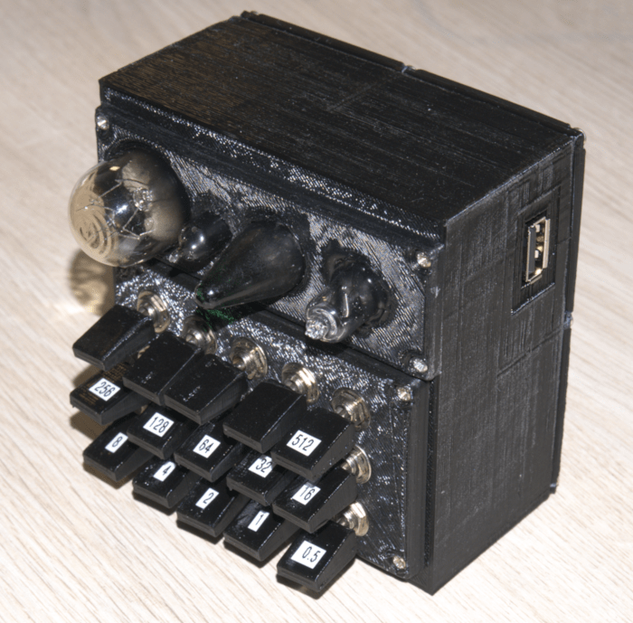
Logically there is series of resistors that increase in resistance in the power of 2: 0.5, 1, 2, 4, 8, 16, 32, 64, 128, 256, 512. Each resistor can be enabled or disabled by a switch. This makes entire range of 0 – 1023.5 ohms available with the 0.5 ohms precision.
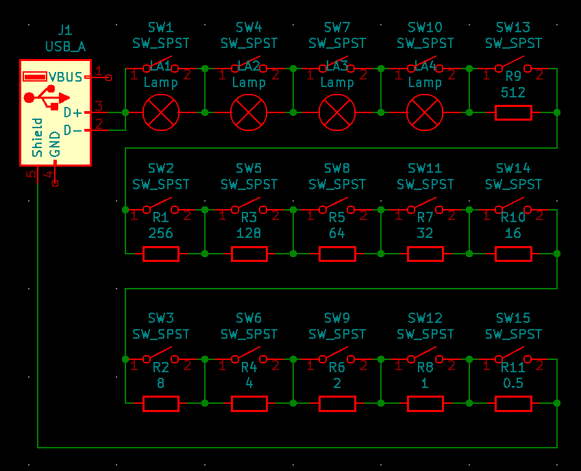
Schematic:
Here is front panel for switches:

Download:
Sometimes I would like to use lightbulbs with various parameters as test load/indicator. Current device has 4 of them included.
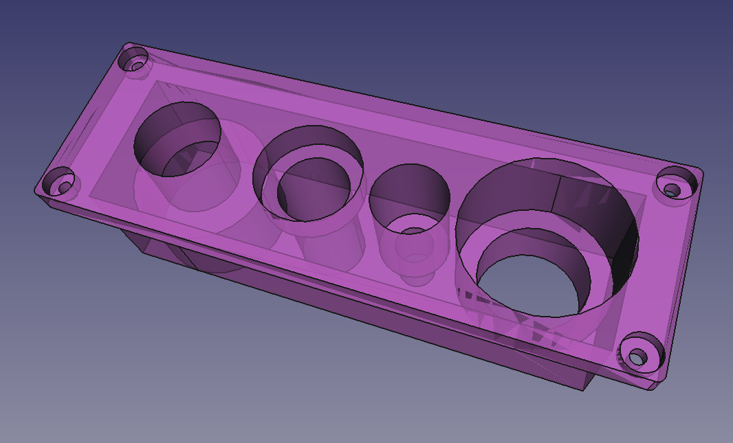
Here is front panel for light bulbs:
Download:
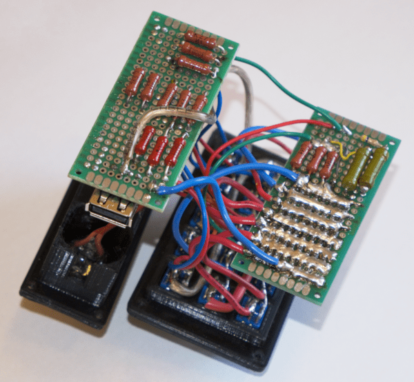
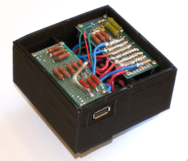
After assembly using prototype PCB:
Following body is used as a case and PCB support:
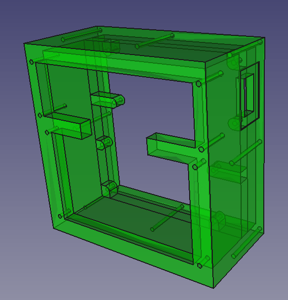
Download:
Result:
Cover on the back:
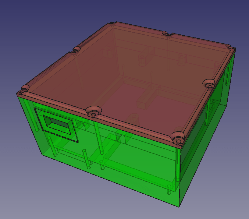
Download: STL file
Button covers:
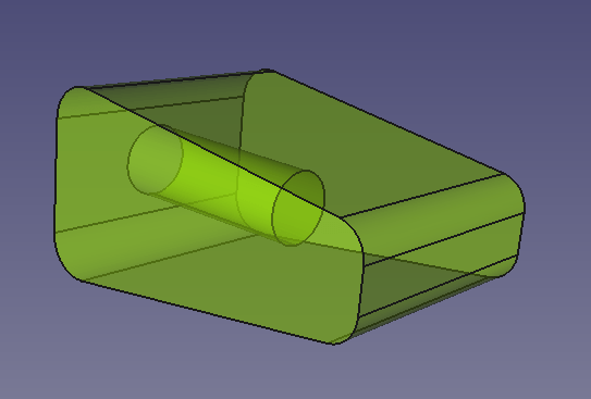
Download:
2. Repository
- Designs in this repository are released under Creative Commons Zero (CC0) license.
- Author:
- Svjatoslav Agejenko
- Homepage: https://svjatoslav.eu
- Email: svjatoslav@svjatoslav.eu
- See also:
2.1. Git repository
- Download latest snapshot in TAR GZ format
- Browse Git repository online
Clone Git repository using command:
git clone https://www2.svjatoslav.eu/git/physical.git