Battery charger and dual power supply unit
1 General
- DISCLAIMER: I DO ELECTRONICS AND 3D DESIGN SOLELY AS A HOBBY. THERE COULD BE ERRORS THAT CAN RESULT IN ALL KINDS OF DAMAGE. USE THESE DESIGNS AT YOUR OWN RISK.
- This design is released under Creative Commons Zero (CC0) license.
- Authors:
- Svjatoslav Agejenko
- Homepage: https://svjatoslav.eu
- Email: svjatoslav@svjatoslav.eu
- Valeria Agejenko
- Svjatoslav Agejenko
- See also:
2 Project description
I needed dual voltage power supply for my lab that runs on mains electricity (wall power) and slowly charges (use-changing) attached 12V Lead-Acid battery. Lead-acid battery in turn provides high current when needed as well as power in portable situations or when mains electricity is not available.
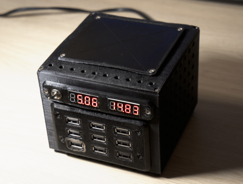
Power supply provides about 13 Volts and 5 Volts simultaneously.
!!!WARNING!!! Alternative and incompatible USB wiring/layout is being used here.
Normal USB devices and cables should not be plugged in! It would damage device/cable and likely power supply.
I found USB-A connectors to be easily available, cheap, reliable and functional, so I re-purposed connector for my own needs but I'm using totally incompatible electrical wiring.
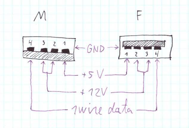
As seen, it has dual voltage output. Additionally one wire is dedicated to data transmission and can be used with 1-Wire protocol
1-Wire data router/hub is really simple. Power supply simply passively links all data wires together.
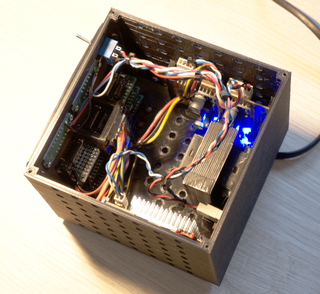
Power supply uses 3D printed body with lots of holes, for fanless cooling.
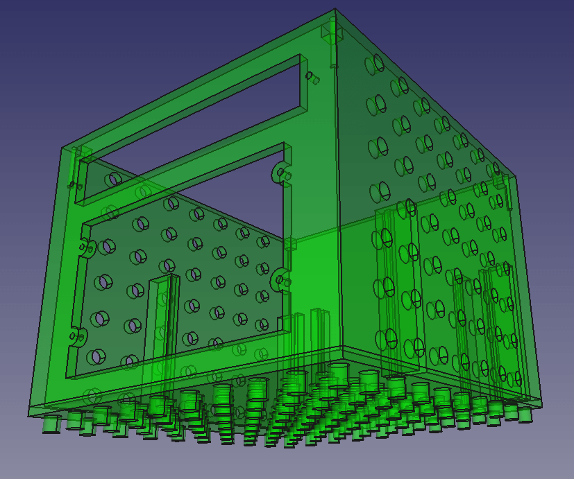
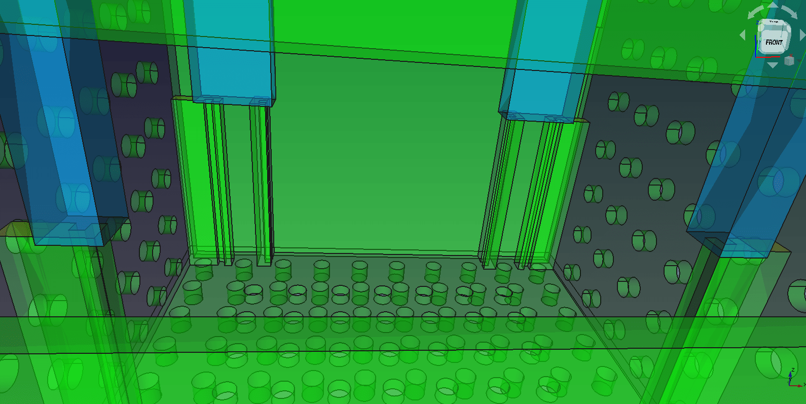
Various modules are realized on top of prototype PCBs that slide into dedicated rails within the body.
Like this:
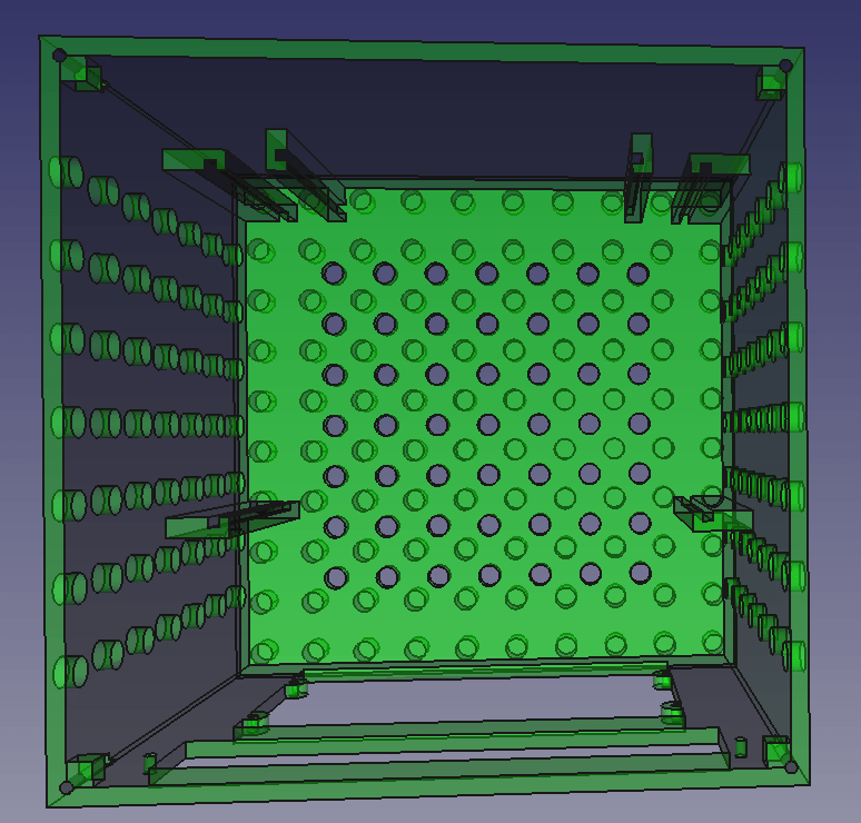
When cover is closed, it blocks PCB movement:
There is still some empty space inside, so why not add dummy cover on top that can be replaced later with add-on functionality/expansion board/terminal :)
Download:
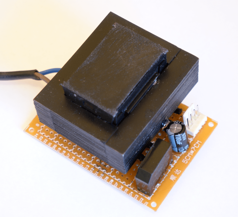
3 Transformer and AC to DC converter
This is where high voltage from mains electricity enters the system.
Schematic:
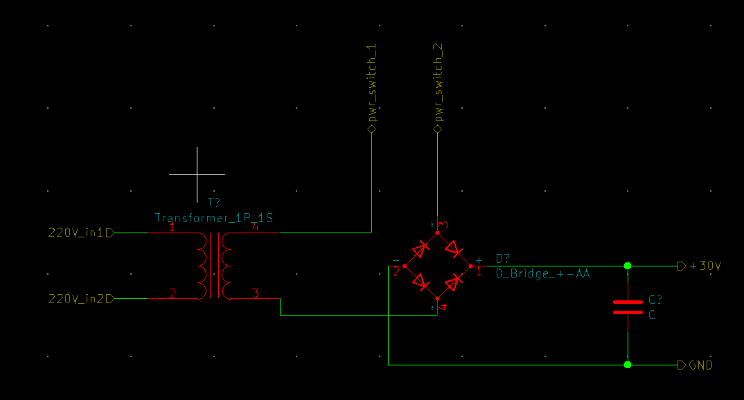
For safety I kept high voltage section as minimal as possible. That is, wall plug runs straight into transformer. Also I used UV hardening glue for extra safety and isolation on PCB.
Power on/off switch operates on already reduced voltage of about 30 volts. Power switch is located on indicator panel.
DC current of about 30 volts is then routed to Main board.
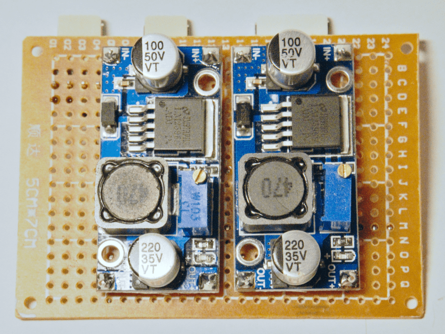
4 Main board
This is logically main board because it appears to be central hub that connects all components. It also houses 2 adjustable DC-DC Step Down voltage converters.
High-level schematic of entire device:
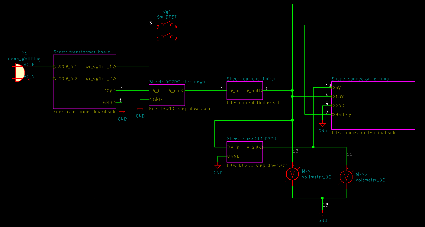
As seen from schematic, ~30 volts DC from transformer board is routed into first step-down converter that reduces it to about 15V. Reduced voltage is then directed to Current limiter circuit. Current limiter loses about 2 volts. Now we have current and voltage limited power at about 13 volts. This power is used to charge connected 12V Lead-Acid battery. Also the same power is routed to connector terminal to be consumed by connected devices.
As seen from this schematic, device is not meant to provide high current for long periods of time. Instead it gets comparatively limited current to charge the battery and feed devices with low current requirements. Occasional current spikes are backed up by battery that stays in use-changing mode.
Also about 13V output voltage is approximate and depends on connected battery charge level.
Second Step-Down converter reduces voltage even further to quite precisely 5V DC. This resulting voltage is also routed to connector terminal.
Both 13V and 5V lines are also routed to indicator panel for monitoring.
There is single on/off switch. In off position, it disconnects battery and transformer from the system effectively powering everything down.
On schematic above, some wires are annotated with numbers from 1 to 13. This corresponds to output pins on the board.
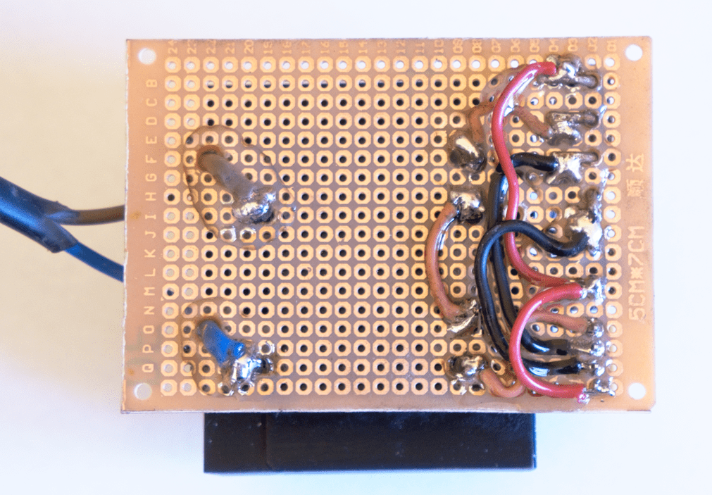
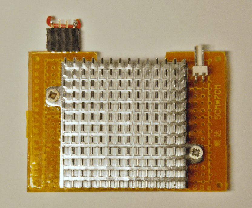
5 Current limiter
Schematic:
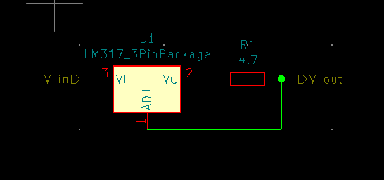
Simple LM317 based current limiter is used. I used 4.7 ohm resistor. It provides about 265 milliamps of current. See calculator.
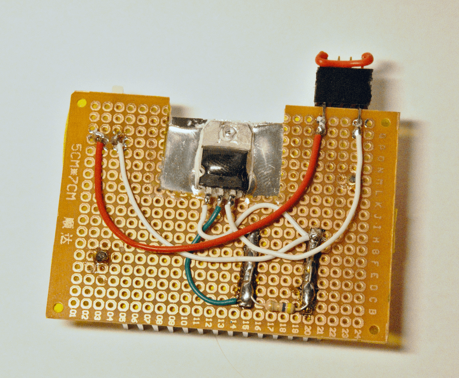
Thermal paste below and UV hardening glue on top is used to attach LM317 to the heatsink. There is also jumper-like solution on top right. This is handy to attach multimeter tap to verify/monitor current during initial device calibration.
If attached battery is really empty, significant voltage drop can occur in LM317. Heatsink is needed to dissipate that power.
Note: resistor gets hot too.
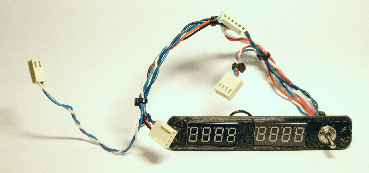
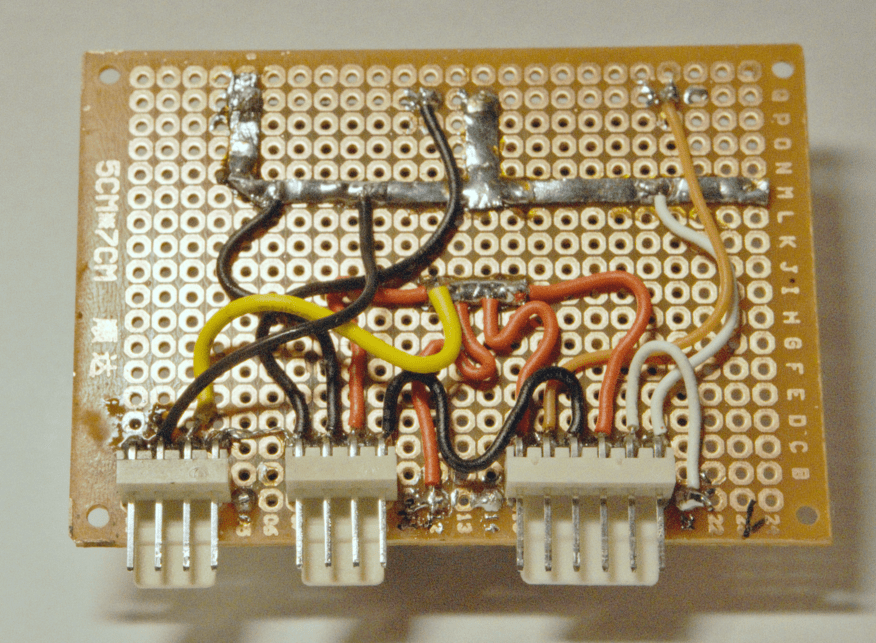
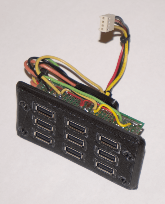
7 Connector terminal
Schematic:
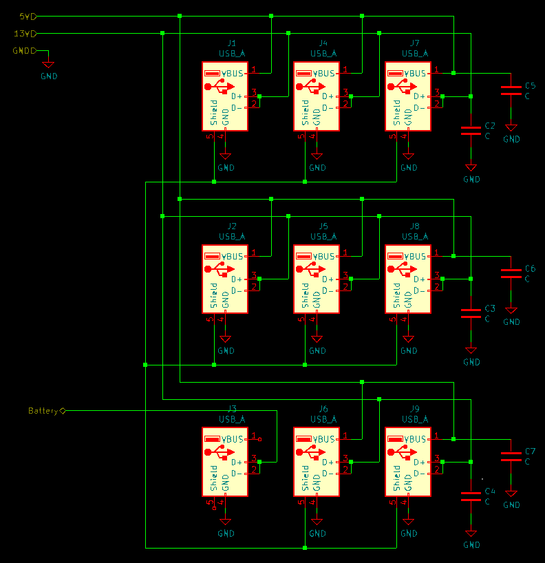
As seen above, most of the USB connectors are used to deliver dual power output and 1-wire data connectivity, except one on the bottom right. This is used to attach 12V battery. Some capacitors are thrown in as well to stabilize against smaller current spikes.
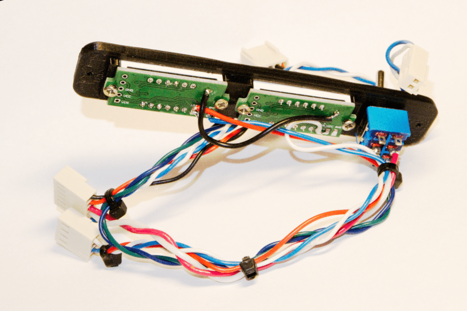
Electrically schematic is realized using smaller prototype PCBs.
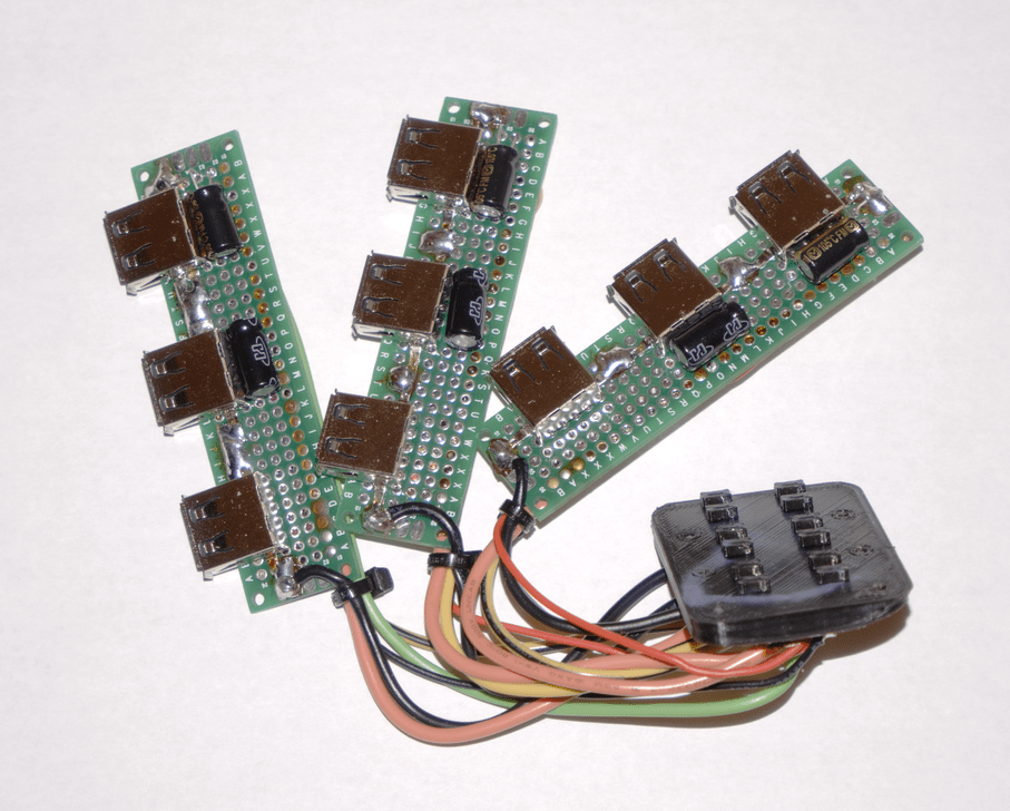
Those PCBs are wired to central small PCB that acts as a hub:
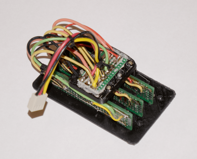
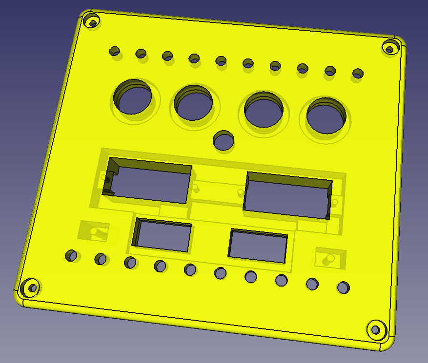
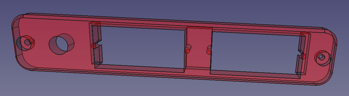
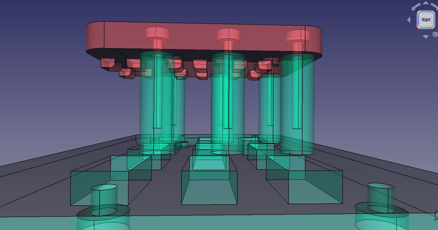
PCBs are held together by being sandwiched between front panel:
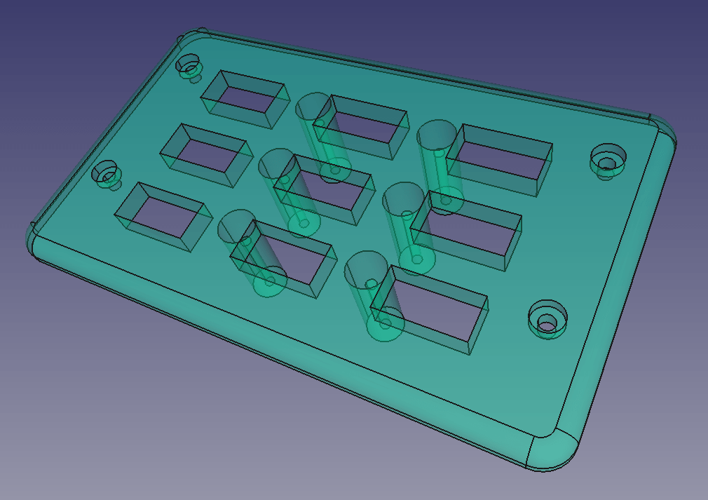
and smaller back-end plate:
Result:
Download:
8 Calibration
Since device uses adjustable step-down modules, these need to be calibrated to provide correct output voltage. It is important that battery receives proper charging voltage otherwise either no charging occurs or battery starts gassing out and gets destroyed.
See here for more details: https://www.powerstream.com/SLA.htm
Happy building! :)