Portable stereo speaker
1 General
- DISCLAIMER: I DO ELECTRONICS AND 3D DESIGN SOLELY AS A HOBBY. THERE COULD BE ERRORS THAT CAN RESULT IN ALL KINDS OF DAMAGE. USE THESE DESIGNS AT YOUR OWN RISK.
- This design is released under Creative Commons Zero (CC0) license.
- Author:
- Svjatoslav Agejenko
- Homepage: https://svjatoslav.eu
- Email: svjatoslav@svjatoslav.eu
- See also:
2 Project description
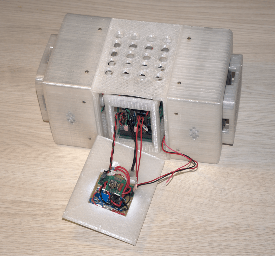
I had pair of good compact stereo speakers lying uselessly around as well as secondhand TDA2030 Chinese knockoff audio amplifier chips. Also I wanted to test modular construction approach: motherboard with shared bus and functionality realized via pluggable modules. So I built stereo speaker:
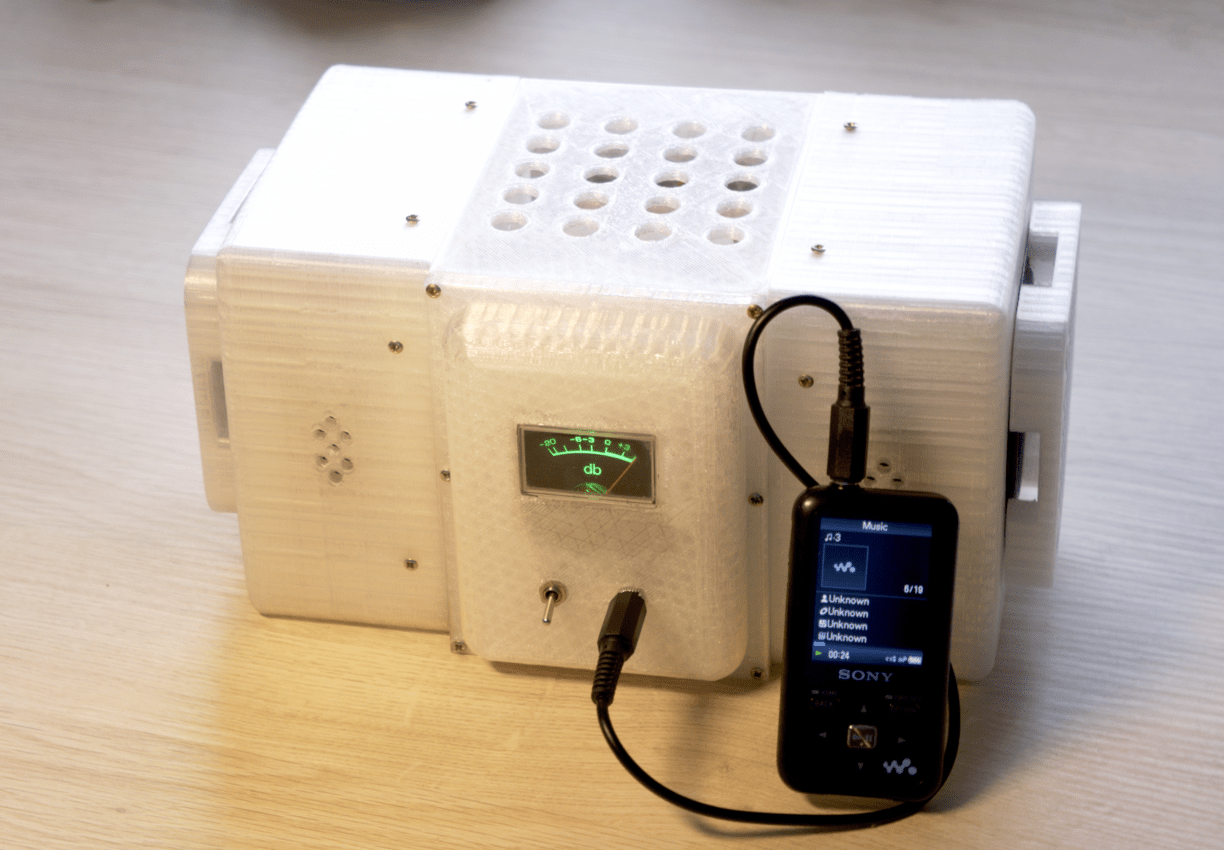
Indicator on the front panel shows available power within the system. Ideally it should be at the maximum. It drops when batteries run empty or when consumed power (too loud music) is greater than onboard power supply or batteries can handle. It has on/off switch and stereo audio input. Audio input impedance is about 100 ohms.
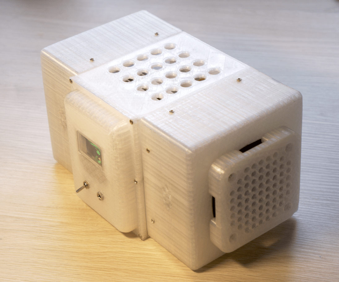
Idea for the holes on the top and smaller ones on the bottom back is to enable air flow for passive cooling.
Entire construction is made of parts, no larger than 120x120x120mm. Maximum for my printer.
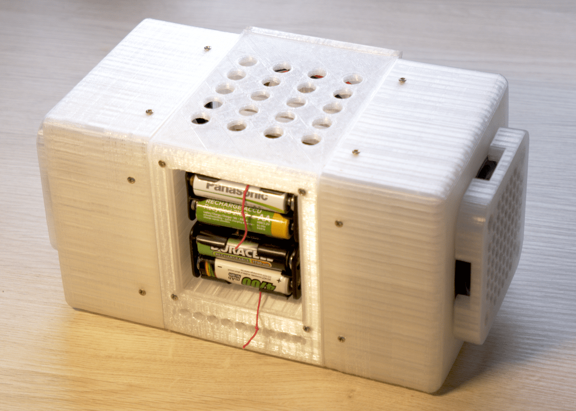
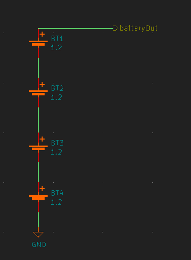
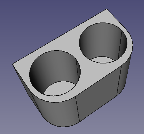
3 Battery holder
Device is powered by 4 times AA NiMH batteries (1.2V each).
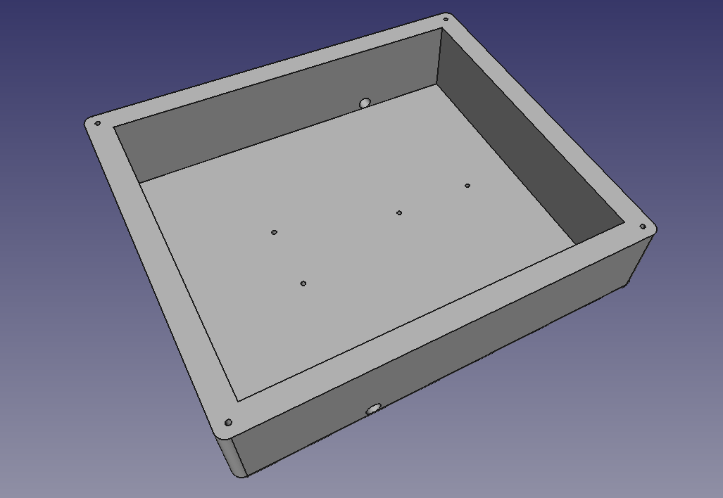
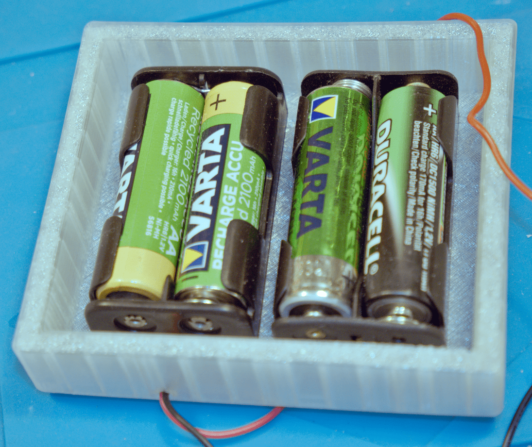
I happened to have AA battery adapters lying around with different bottom hole configurations. Therefore this weird hole design:
Download:
Result:
Attaches to the back of the body:
4 20V up-step module
Battery pack voltage is routed through main on/off switch on the front panel, and then it goes to the 20V up-step module.
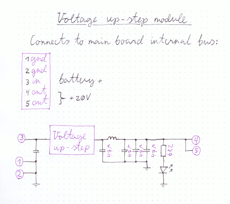
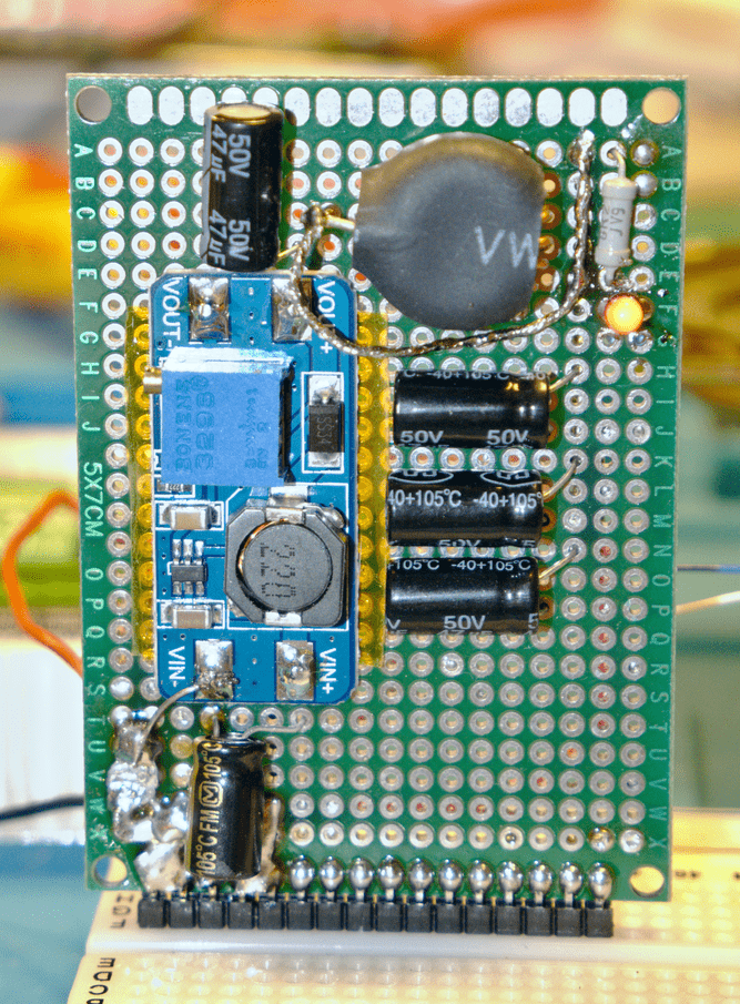
It uses ready made upstep module, but adds extra voltage filtering via inductor and capacitors.
5 Main board
Voltage upstep above sits on top of main board (motherboard). It has uniform central bus that spans all connectors.
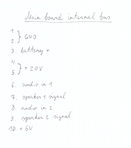
First row of the main board is special IO terminal (for connecting speakers, front panel, etc..)
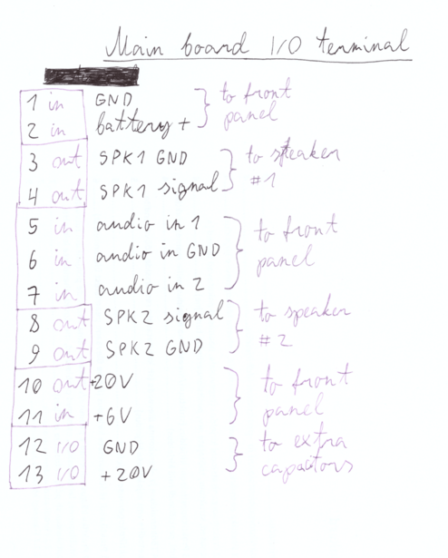
Remaining rows are for connecting boards:
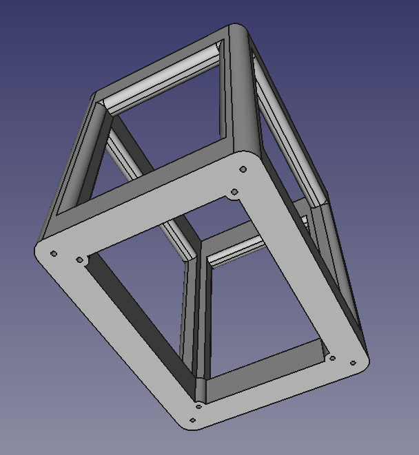
To provide structural support, main board is attached to frame:
Download:
And boards plugged into main board are fixed at the top, using clip:
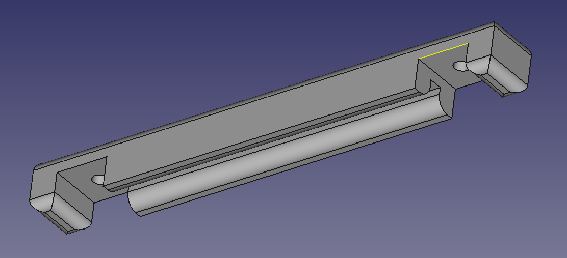
Download:
Result:
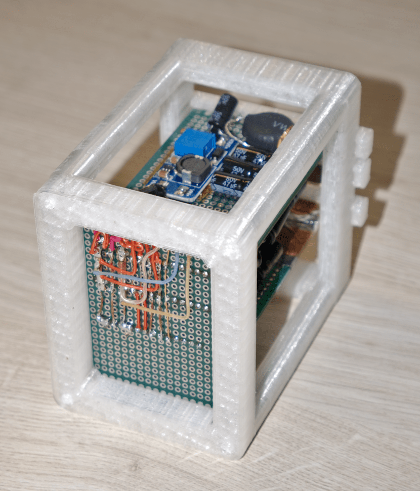
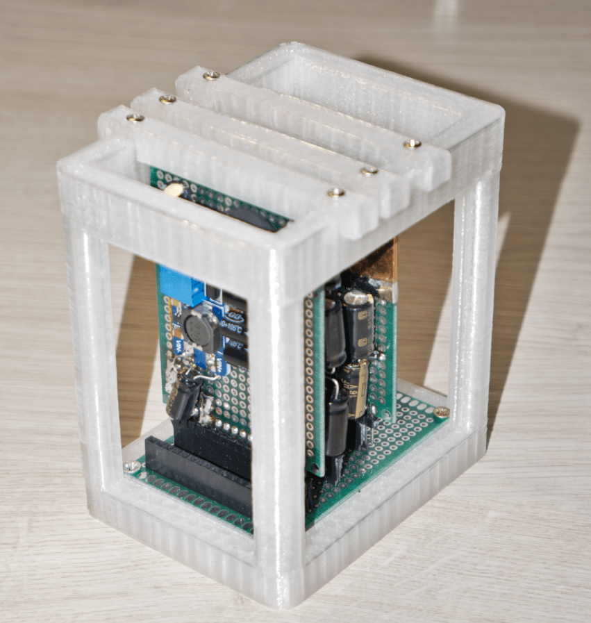
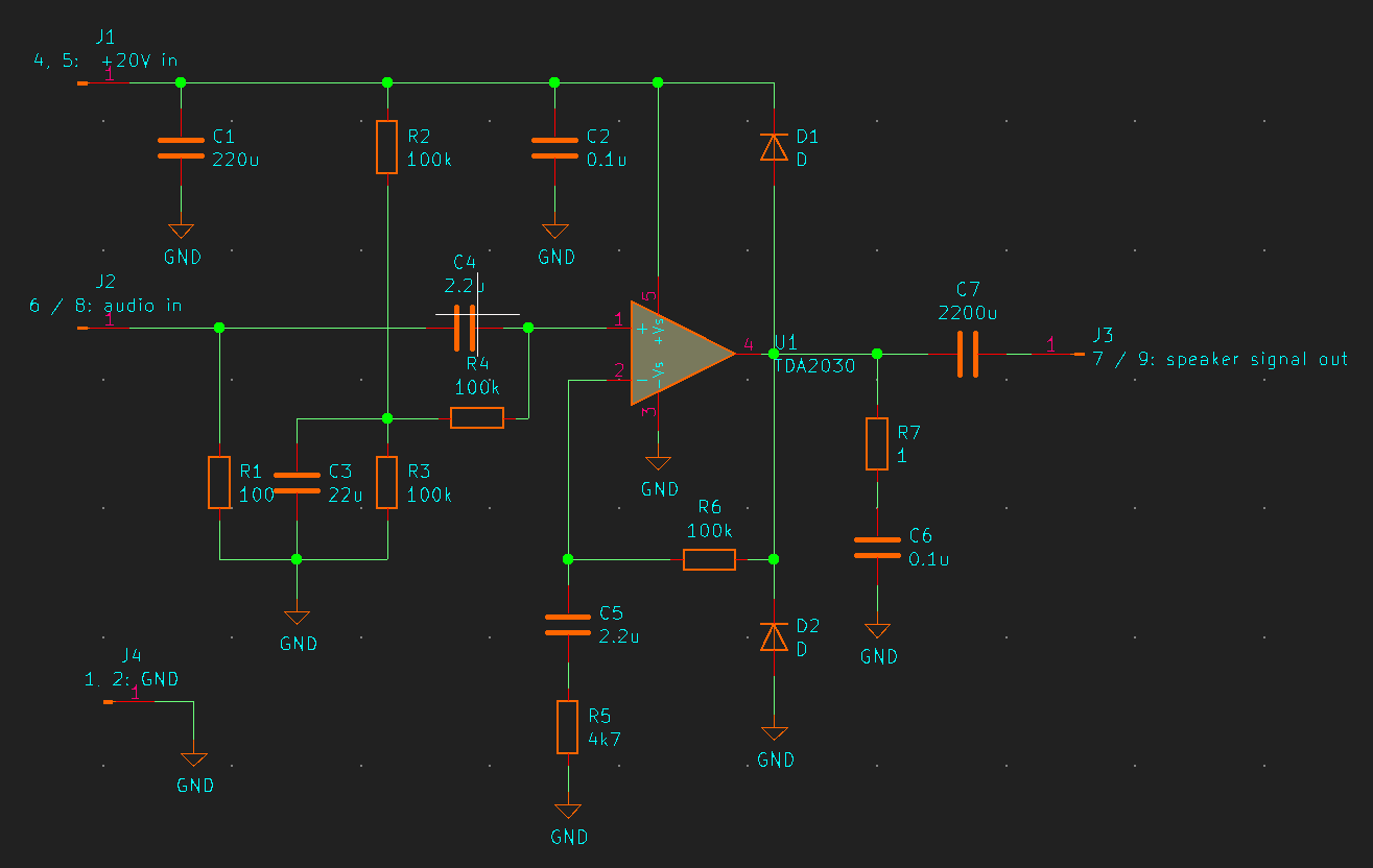
6 Mono audio amplifier module
Design uses scavenged secondhand Chinese TDA2030 audio amp clones. Each chip is mono audio amplifier. Therefore 2 almost identical audio amp modules had to be built, one for left speaker, one for right.
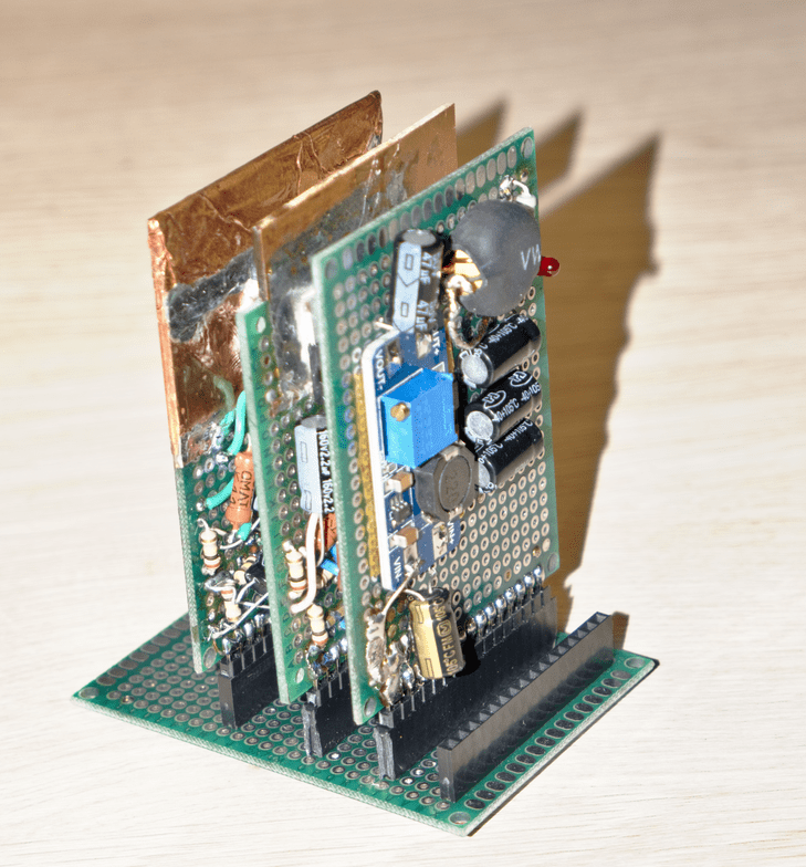
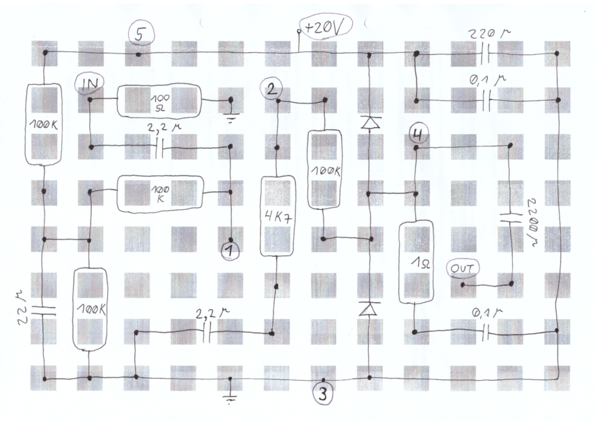
I like to build on top of prototype PCBs. Gives results much faster for one-off projects. Before soldering, I solve component layout on paper:
Result - front:
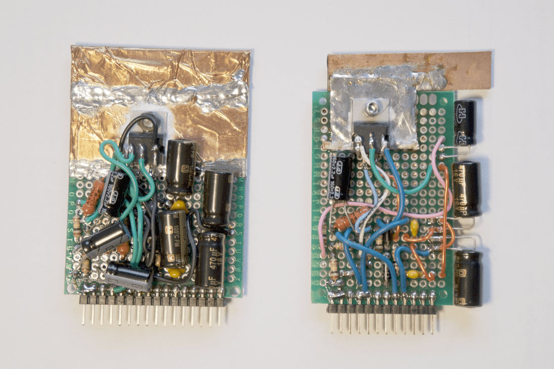
Result - back:
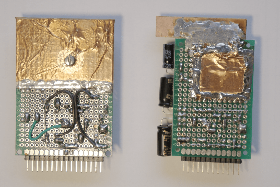
Here copper tape is used as improvised heatsink.
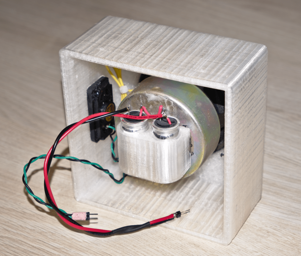
7 Speakers
High frequency small speaker and medium frequency bigger speaker are combined.
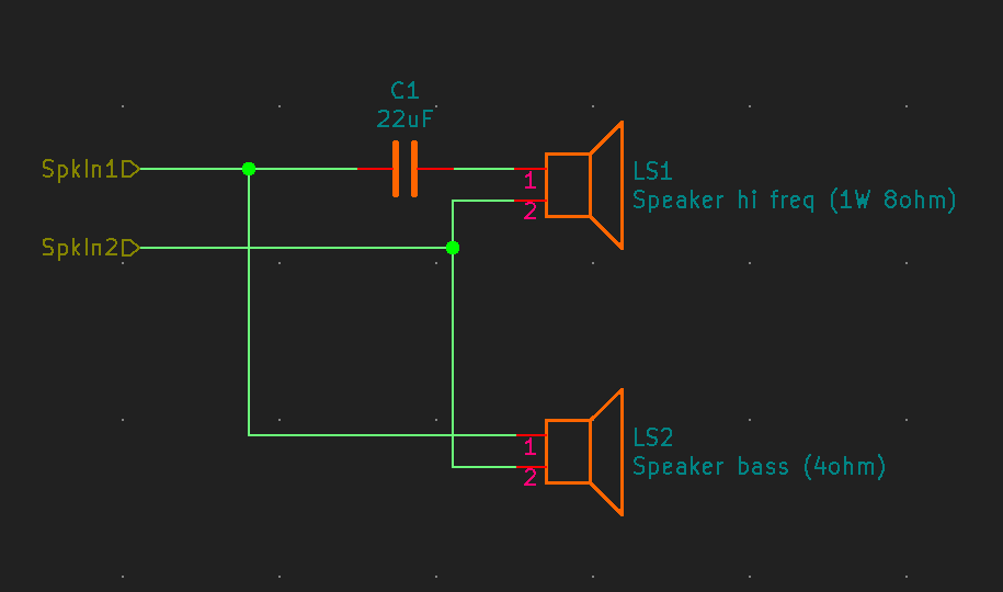
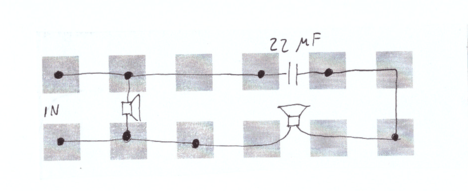
Capacitor acts as high-pass filter on top of tiny PCB:
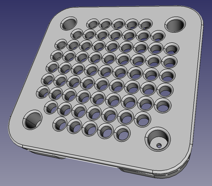
Speaker enclosure:
Download:
Speaker enclosure cover:
Download:
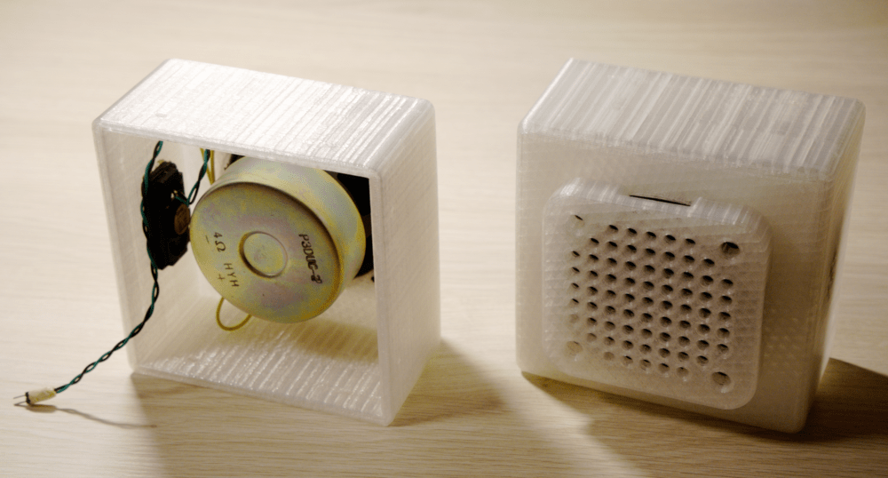
Result:
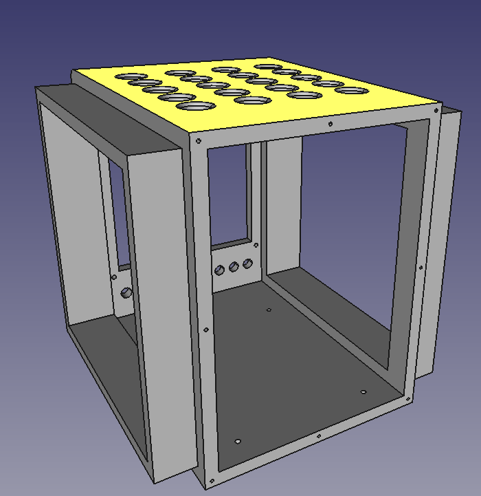
8 Front panel
Initial idea was really simple panel:
- on/off switch
- system power indicator
- stereo audio input
But, since I'm using "agile" approach, during load-testing, it become clear that active fan based cooling would be nice (when playing loud music). I found tiny cooler fan that needs 5 volts to operate. Also I need to power backlight for power indicator. For both of these cases, I decided to add another voltage up-step module (target voltage output set to 6V). This time directly on the front panel.
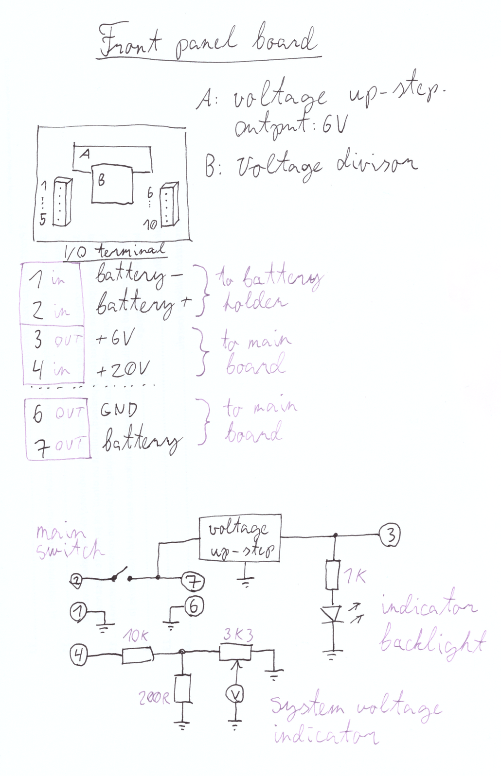
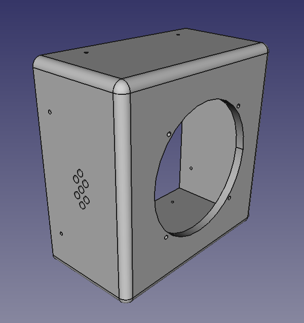
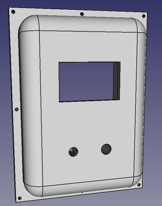
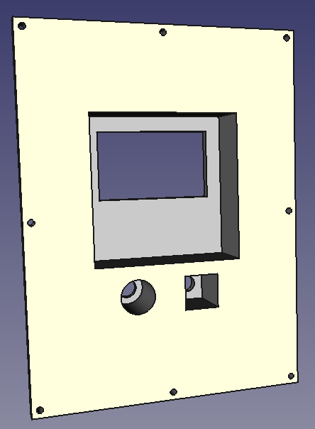
Front panel case:
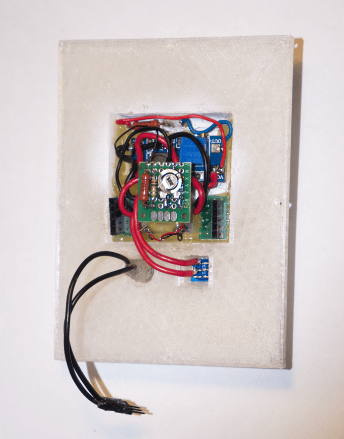
Electronics fits inside:
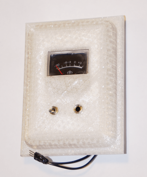
Front view:
And attaches to the remaining components:
9 Extra capacitors
Another thing that become clear during load-testing: output power/volume can be further enhanced by adding high power capacitors to even out load on primary 20V up-step module.
Download:
Extra caps are mounted on top of the speaker and electrically attached to the main board.
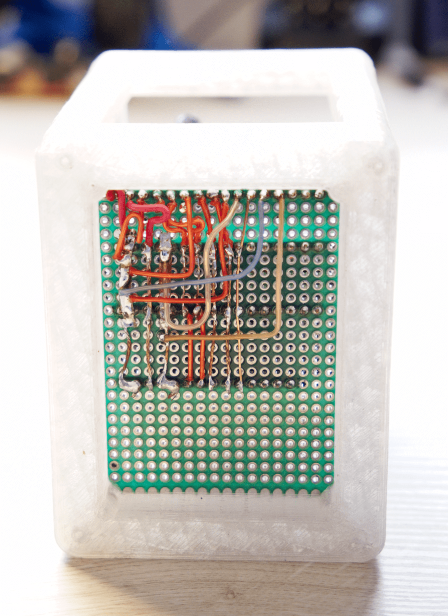
10 Center box
Last physical part, to attach it all together: central body.
Front:
Back:
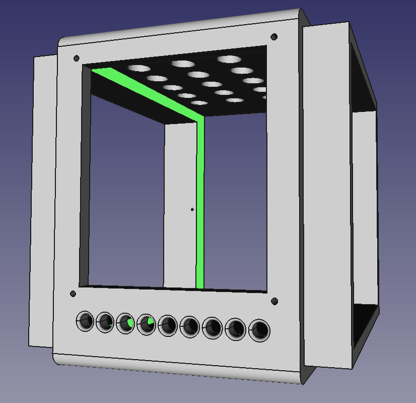
Download:
11 Conclusions / TODO
These things could be done better:
- Instead of using undersized heatsinks on the audio amplifiers and need for active cooling as a consequence, it would be better to try to mount audio amplifier chip on top of speaker metallic body. It would provide plenty of cooling and reduces power losses within cable, since amplifier would be as close to the speaker as possible.
- I used agile design. That is, implemented functionality ad-hoc. If I had done design in advance, then I could have had smarter connector layout between main board and front panel. That is: Instead of multiple smaller cables, one wide (multi connector) cable.
- Screw holes are too close to the edges on the front panel.
- It would be better if screw heads were slightly buried within construction body.
Overall, it was good learning experience and I was able to test various ideas on it. Will add cooler later :)
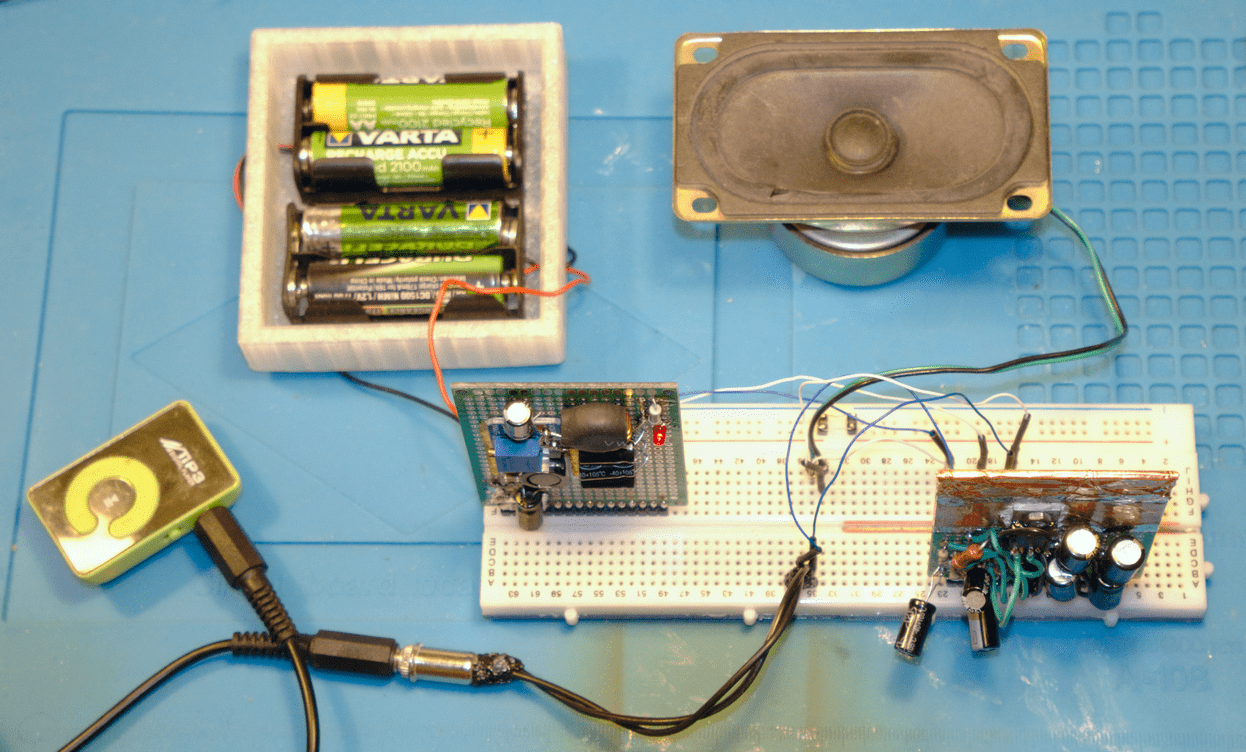
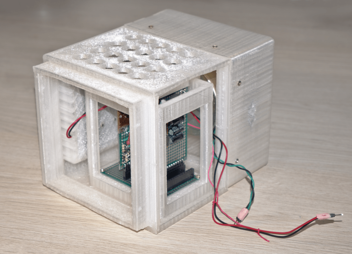
Photo of initial PSU + audio amp test: