LPT Communication Driver
Table of Contents
1. Overview
This is weird networking solution. It allows to send data using parallel LPT port serially(!) by bit-banging between two connected computers :)
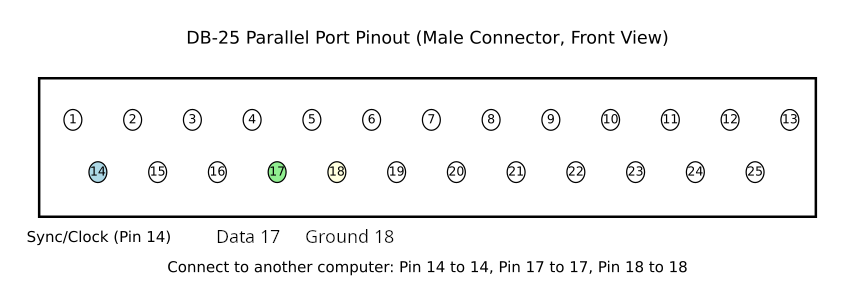
Out of 25 physical wires in LPT port, only 3 are used:
- Pin 14
- Carries a synchronization signal which uses a periodic pattern (e.g., 010101…) to maintain timing alignment between the communicating computers.
- Pin 17
- Functions as the bidirectional data line, responsible for transmitting and receiving data between the connected computers.
- Pin 18
- Acts as the ground connection, providing a common reference for electrical signals to ensure consistency in communication.
By utilizing only three wires and software controlled bit-banging algorithm, custom, comparatively simple, cheap and long cable can be built to connect 2 computers in a DIY network setup.
2. LPT Communication Driver
2.1. Overview
The LPT Communication Driver is a Terminate and Stay Resident (TSR) driver designed to facilitate communication between computers using parallel printer ports (LPT). This driver uses bit-banging to send and receive data serially over the LPT port, utilizing only three wires for communication.
Driver hooks into the system's IRQ 0 to ensure that system timer always keeps executing it in the background. While operating as a background process, it periodically monitors LPT port to detect incoming transmission. When transmission is detected, driver receives, decodes and stores it into preallocated 5000 byte receive buffer.
Applications can then communicate with the driver on their own schedule using INT 63h to poll for and retrieve received messages, if any. Applications can also send outgoing messages into 5000 byte driver outbox memory buffer. Thereafter driver will transmit those messages in background mode over the wire.
The driver is half-duplex: it prioritizes receiving over sending and does not transmit while receiving.
During active transmission/reception, the driver can consume 100% CPU due to busy-wait loops in the IRQ handler, potentially causing random temporary hiccups for application running in the foreground. Unsuitable for real-time systems.
Download:
- Source code: lptdrv.asm
- Compiled binary: lptdrv.com
2.2. Data transmission implementation details
When there is incoming data transmission, the TSR driver detects it during its periodic execution in the IRQ 0 (timer) handler, which runs approximately every 55ms.
Driver checks for possible transmission comparatively rarely (every 55 ms) and for this reason it is important to have quite long transmission start indicator/header before actual data is sent. This allows long enough time for recipient computer communication driver to detect that transmission line is active and start listening to it now in exclusive busy-wait loop. So, the TSR driver steals 100% of the CPU for the duration of transmission.
The start of transmission is detected by reading the port (37Ah) value, and checking if bit 3 of the raw input is high. It then enters a "skip header" loop. Once bit 1 goes low, bit reception begins. The end is detected via a timeout: during bit reception, a counter increments on each poll. If there is no change in the port value for 30 consecutive polls (indicating no new bit transition), it assumes the transmission is complete, appends a 2-byte length to the receive buffer, and exits the routine.
So, both receive and send routines execute within the IRQ 0 handler using busy-wait polling loops (for receive) or timed output loops (for send). These can hold the CPU for the full duration of a transmission, as the handler does not yield until complete.
It bit-bangs data by treating the LPT control port (37Ah) as both output and input, using bit 3 (pin 17, data line) for the serial data bit and bit 1 (pin 14, sync line) for a clock that alternates (low on even bit indices, high on odd) to signal transitions.
For sending: the port is first set to 0xFF (all bits high) as a header, held for ~110ms (2 timer ticks).
For receiving: after start detection, it polls the port for value changes (transitions). On each change, it reads the port again (to ensure that synchronization bit did not arrive ahead data bit over the separate physical wire), extracts bit 3 as the data bit, shifts it into a byte accumulator, and resets the timeout counter. Once a full byte is accumulated, it stores it in the receive buffer. No ACK or error checking.
Driver can receive multiple transmissions into its 5000-byte receive buffer before the client program reads it out. Each incoming transmission appends its data bytes followed by a 2-byte length word directly to the end of the buffer (updating dbufsiz to the new total used). As long as the cumulative size doesn't exceed 5000 bytes, multiple can queue up. The buffer acts as a FIFO for concatenated packets; overflows are not handled (it would corrupt without checks). The client retrieves the entire buffer contents at once when polling.
When the client program reads received data from the TSR (via INT 63h AH=2), the driver copies the full buffer contents (up to dbufsiz bytes) to the client's specified ES:DI pointer, returns the byte count in AX, and immediately resets dbufsiz to 0, clearing the buffer. This ensures the data is not served again on subsequent reads, as the buffer is emptied after each retrieval. If no data is available, AX=0 is returned.
2.3. Driver API
The driver uses INT 63h for its API, with functions selected via the AH register. It maintains two internal buffers:
- Download Buffer: 5000 bytes for incoming (received) data. Multiple transmissions can be queued here, each appended with a 2-byte length footer.
- Upload Buffer: 5000 bytes for outgoing (to-be-sent) data. Data is copied here and transmitted when the line is free.
Communication is polling-based for applications; the driver handles transmission/reception in the background.
No error checking, acknowledgments, or flow control; it's a simple, unidirectional-per-turn protocol.
To use the driver:
- Load the TSR (e.g., run lptdrv.com).
- Activate it via the API.
- Poll for received data or queue sends as needed.
- Deactivate when done.
API overview:
| AH register | API function |
|---|---|
| 0 | Deactivate the driver |
| 1 | Activate the driver |
| 2 | Retrieve downloaded data from the driver's input buffer |
| 3 | Upload data to the driver's output buffer for transmission |
2.3.1. Deactivate the driver
Disables the driver, stopping background monitoring and transmission. The LPT port is reset (set to 0).
- AH: 0
- Parameters: None
- Returns: None
- Side Effects: Clears the enabled flag.
- Usage Notes: Call this before unloading the TSR or when communication is no longer needed to free system resources.
2.3.2. Activate the driver
Enables the driver, starting background LPT port monitoring for incoming data. The LPT port is reset (set to 0) upon activation.
- AH: 1
- Parameters: None
- Returns: None
- Side Effects: Sets the enabled flag. Existing buffer contents are preserved.
- Usage Notes: Must be called after loading the TSR and before any send/receive operations. Can be called multiple times; redundant activations are harmless.
2.3.3. Retrieve downloaded data from the driver's input buffer
Copies all accumulated received data from the driver's download buffer to the caller's memory location and clears the buffer.
- AH : 2
- Parameters :
- ES:DI : Pointer to the buffer where received data should be copied (must be large enough to hold up to 5000 bytes).
- Returns :
- AX : Number of bytes copied (0 if no data available).
- Side Effects : Resets the download buffer size to 0, preventing re-retrieval of the same data.
- Usage Notes :
- Data is retrieved as a concatenated stream of all queued transmissions.
- Each transmission in the buffer ends with a 2-byte length word (little-endian) indicating its payload size (excluding the length itself).
- Poll this function periodically in a loop to check for new data.
- If AX=0, no copy occurs.
- Example: In assembly, set ES:DI to your receive buffer and call INT 63h; then process AX bytes if >0.
2.3.4. Upload data to the driver's output buffer for transmission
Copies the specified data to the driver's upload buffer for background transmission. Transmission occurs when the line is free (no incoming data).
- AH : 3
- Parameters :
- DS:SI : Pointer to the data to upload.
- CX : Number of bytes to upload (must not exceed remaining upload buffer space; no checks performed).
- Returns : None
- Side Effects : Appends data to the upload buffer and updates its size. Transmission is asynchronous.
- Usage Notes :
- Data is sent as a single transmission (no automatic framing; caller can add headers if needed).
- If the buffer is full (total >5000 bytes), behavior is undefined (overflow).
- Multiple calls can queue data sequentially in the buffer.
- Transmission starts in the next IRQ 0 tick if the line is idle.
- The driver adds no footer; the receiver sees exactly the sent bytes.
- Example: Load DS:SI with your message, CX with length, call INT 63h; the driver handles sending.