Shading & Lighting - Sixth 3D
Table of Contents
1. Overview
Sixth 3D implements flat shading using the Lambert cosine law. Each polygon receives a single color based on its orientation relative to light sources. This is a simple yet effective lighting model that gives 3D objects depth and realism.
1.1. The Lighting Model: Lambert Cosine Law
The Lambert cosine law determines how much light a surface receives based on its orientation. A surface facing directly toward a light source receives maximum illumination; as it tilts away, the illumination decreases proportionally until it reaches zero when perpendicular to the light direction. This fundamental principle creates the visual cues that make 3D objects appear solid and dimensional rather than flat.
The engine implements this law through the dot product of two vectors. The LightingManager computes a unit vector pointing from the polygon's center to each LightSource, then calculates the dot product with the surface normal. When the dot product equals 1.0, the surface faces the light directly and receives full brightness. At 0.71 (a 45-degree angle), it receives about 71% illumination. At zero or below, the surface faces away from the light and receives no direct contribution from that source. The implementation in LightingManager.computeLighting() explicitly checks for positive dot products before adding light contributions, ensuring that back-facing surfaces skip unnecessary calculations.
The surface normal itself is computed by Plane.computeNormal(), which takes the first three vertices of a polygon and calculates their cross product to find the perpendicular direction. This normal, along with the polygon's center point calculated by SolidPolygon, is passed to the lighting manager during the transform phase of the rendering loop. Computing lighting during this single-threaded phase ensures thread safety and allows the result to be cached in the polygon's reusable shadedColor field, avoiding memory allocation during the subsequent multi-threaded paint phase. See the Normal Vector section for more details on how normals are computed and used throughout the engine.
2. Light Sources
Each light source has three properties:
| Property | Description |
|---|---|
| Position | 3D world coordinates of the light |
| Color | RGB color of emitted light |
| Intensity | Brightness multiplier (1.0 = normal) |
import eu.svjatoslav.sixth.e3d.renderer.raster.lighting.LightSource;
import eu.svjatoslav.sixth.e3d.geometry.Point3D;
import eu.svjatoslav.sixth.e3d.renderer.raster.Color;

// Create a bright yellow light to the right
LightSource rightLight = new LightSource(
    new Point3D(200, -100, 0),  // position: right, above, at viewer level
    Color.YELLOW,               // color
    2.0                         // intensity: extra bright
);

// Create a dim blue light from the left
LightSource leftLight = new LightSource(
    new Point3D(-150, 50, 100),
    Color.BLUE,
    0.5                         // intensity: dim
);
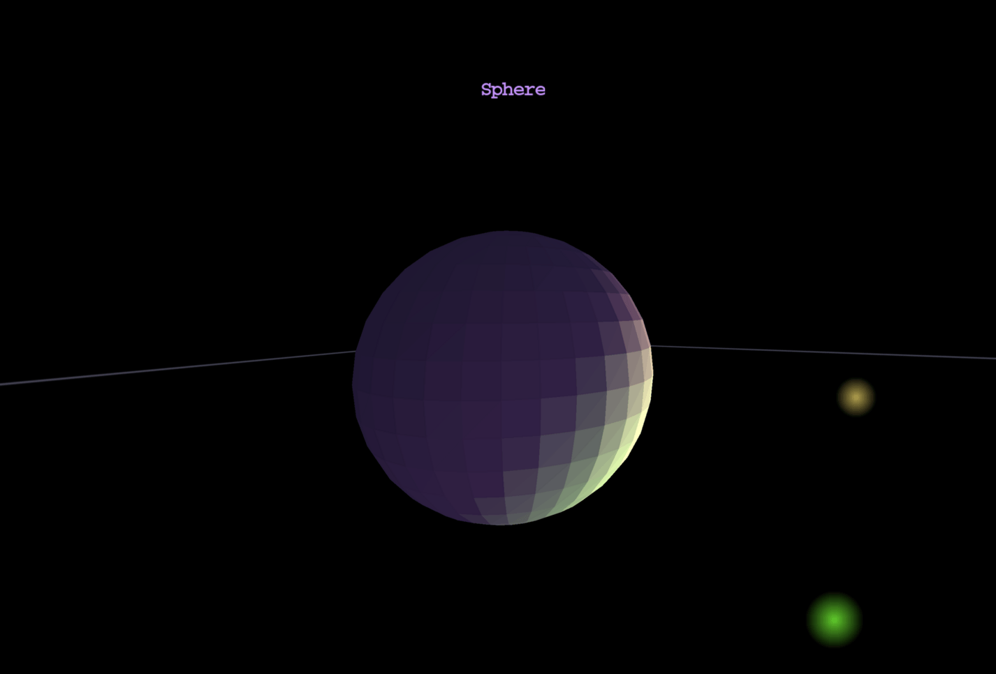
Multiple light sources add their contributions together, allowing for complex lighting setups like the screenshot above showing a sphere lit by two lights from the right.
2.1. Distance Attenuation
Light intensity decreases with distance using a simplified inverse square law:
attenuation = 1.0 / (1.0 + 0.0001 * distance²)
- At distance 0: attenuation = 1.0 (full intensity)
- At distance 100: attenuation ≈ 0.99 (almost full)
- At distance 300: attenuation ≈ 0.52 (half intensity)
- At distance 500: attenuation ≈ 0.29 (about 30%)
This simplified formula prevents harsh cutoffs while still providing
distance-based dimming. The 0.0001 coefficient was tuned for typical
scene scales in Sixth 3D.
3. Ambient Light
Ambient light provides base illumination that affects all surfaces equally, regardless of orientation. Without ambient light, surfaces not directly facing a light source would be pure black.
- Default ambient:
Color(50, 50, 50)(dim gray) - Configurable via
lightingManager.setAmbientLight() - Too much ambient: flat appearance (no contrast)
- Too little ambient: harsh shadows (pure black areas)
// Increase ambient for softer shadows
viewPanel.getLightingManager().setAmbientLight(new Color(80, 80, 80));

// Reduce ambient for dramatic contrast
viewPanel.getLightingManager().setAmbientLight(new Color(20, 20, 20));
4. Using Shading in Your Scene
Adding light sources:
import eu.svjatoslav.sixth.e3d.gui.ViewPanel;
import eu.svjatoslav.sixth.e3d.renderer.raster.lighting.LightSource;

ViewPanel viewPanel = new ViewPanel();

// Get the lighting manager
LightingManager lighting = viewPanel.getLightingManager();

// Add light sources
lighting.addLight(new LightSource(
    new Point3D(200, -100, 0),  // right side, above
    Color.YELLOW,
    1.5                         // bright
));

lighting.addLight(new LightSource(
    new Point3D(-100, 0, 200),  // left side, further away
    new Color(255, 200, 150),   // warm white
    1.0
));

// Configure ambient light
lighting.setAmbientLight(new Color(40, 40, 40));
Enabling shading on shapes:
import eu.svjatoslav.sixth.e3d.renderer.raster.shapes.composite.solid.SolidPolygonRectangularBox;

// Create a shaded box
SolidPolygonRectangularBox box = new SolidPolygonRectangularBox(
    new Point3D(-50, -50, 100),  // min corner
    new Point3D(50, 50, 200),   // max corner
    Color.RED
);

// Enable shading on the box and all its sub-polygons
box.setShadingEnabled(true);

// Also enable backface culling for closed meshes
box.setBackfaceCulling(true);

// Add to scene
viewPanel.getRootShapeCollection().addShape(box);
Shading propagates through composite shapes — calling setShadingEnabled(true) on a composite enables shading for all its sub-polygons.
5. Implementation details
Lighting is computed during Phase 2 (transform phase) of the rendering loop:
- Each shaded polygon calculates its center point and surface normal
- LightingManager computes lighting from all sources
- Result stored in reusable
shadedColorfield - During Phase 4 (paint), the cached color is used directly
Why during transform phase?
- Transform phase is single-threaded — no race conditions
- Lighting computed once per polygon per frame — not per pixel
- Result reused during multi-threaded paint phase — efficient
5.1. Performance Characteristics
| Aspect | Cost |
|---|---|
| Computation | Per polygon, not per pixel |
| Phase | Single-threaded (transform) |
| Allocation | Zero (reuses Color instance) |
| Cache | One shadedColor per polygon |
The shading implementation is optimized for CPU rendering:
- Flat shading: One lighting calculation per polygon (N-vertex polygon = 1 calculation)
- Reusable Color: Result stored in existing field, no allocation during render
- Thread-safe: Single-threaded transform phase avoids synchronization
- Pre-computed: All 8 paint threads use the same cached result
This approach trades visual fidelity (no per-pixel lighting) for performance — essential for software rendering where per-pixel lighting would be prohibitively expensive.