Aukio 3D - Realtime 3D engine
Table of Contents
- 1. Introduction
- 2. How take engine into use
- 3. Essential theory
- 4. 3D engine internals
- 5. Developer tools
- 6. Agentic development
- 6.1. One pipeline, two drivers
- 6.2. Snapshot: render without a window
- 6.3. PixelAssertions: did this region get painted?
- 6.4. GoldenImage: compare against a reference
- 6.5. SceneDump: the reproducible bug report
- 6.6. HouseGoldens: ready-made regression tests
- 6.7. export-docs.sh: regenerate the documentation
- 6.8. A typical agent session
- 6.9. Related Classes
- 7. Source code
1. Introduction
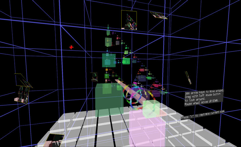
Aukio 3D is a realtime 3D rendering engine written in pure Java. It runs entirely on the CPU — no GPU required, no OpenGL, no Vulkan, no native libraries. Just Java.
The motivation is simple: GPU-based 3D is a minefield of accidental complexity. Drivers are buggy or missing entirely. Features you need aren't supported on your target hardware. You run out of GPU RAM. You wrestle with platform-specific interop layers, shader compilation quirks, and dependency hell. Every GPU API comes with its own ecosystem of pain — version mismatches, incomplete implementations, vendor-specific workarounds. I want a library that "just works".
Aukio 3D takes a different path. By rendering everything in software on the CPU, the entire GPU problem space simply disappears. You add a Maven dependency, write some Java, and you have a 3D scene. It runs wherever Java runs.
This approach is quite practical for many use-cases. Modern systems ship with many CPU cores, and those with unified memory architectures offer high bandwidth between CPU and RAM. Software rendering that once seemed wasteful is now a reasonable choice where you need good-enough performance without the overhead of a full GPU pipeline. Java's JIT compiler helps too, optimizing hot rendering paths at runtime.
Beyond convenience, CPU rendering gives you complete control. You own every pixel. You can freely experiment with custom rendering algorithms, optimization strategies, and visual effects without being constrained by what a GPU API exposes. Instead of brute-forcing everything through a fixed GPU pipeline, you can implement clever, application-specific optimizations.
Aukio 3D is part of the larger Aukio project, with the long-term goal of providing a platform for 3D user interfaces and interactive data visualization. It can also be used as a standalone 3D engine in any Java project. See the demos for examples of what it can do today.
Major features:
1.1. Global Illumination
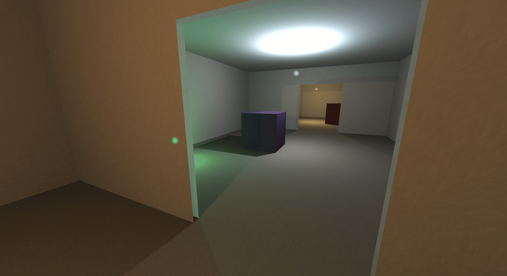
On top of flat shading, the engine computes progressive global illumination on background CPU threads: real shadows, smooth light falloff inside polygons (per-texel lightmaps), and indirect bounce light — while the render loop itself never traces a single ray.
Read more about global illumination.
1.2. Side-by-side stereoscopic rendering support
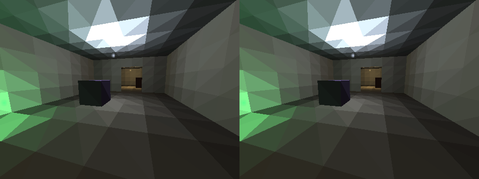
The engine can render every frame twice — once per eye — into the left and right halves of the same image, for XR glasses and 3D displays. The cameras stay parallel and are offset by a configurable IPD (inter-pupillary distance). Two render passes share one triple-buffered pipeline, each clipped to its half of the frame buffer; per-eye projection, frustum culling and mouse picking adapt automatically.
With RayNeo XR glasses the engine also tracks the head: plugging the glasses in over USB auto-starts IMU head tracking, so the stereo image responds to look-around (hot-plug at runtime, Scroll Lock recenters).
See Stereoscopic rendering for the geometry, pipeline and tuning, and its head tracking section for the glasses IMU support.
1.3. SpaceMouse 6DOF input
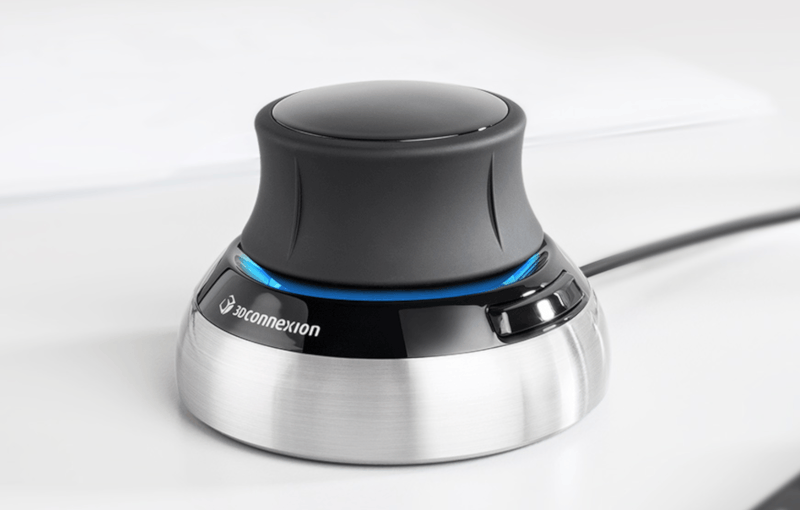
A 3Dconnexion SpaceMouse (SpaceNavigator over USB or SpaceMouse Wireless over Bluetooth) flies the camera with its pressure-sensitive 6DOF cap: push, pull, slide and press to move, tilt and twist to look. Connecting it auto-starts camera control in every application (hot-plug at runtime), composing freely with head tracking and mouse drag.
See SpaceMouse 6DOF for the cap mapping, tuning and device setup.
1.4. Constructive Solid Geometry
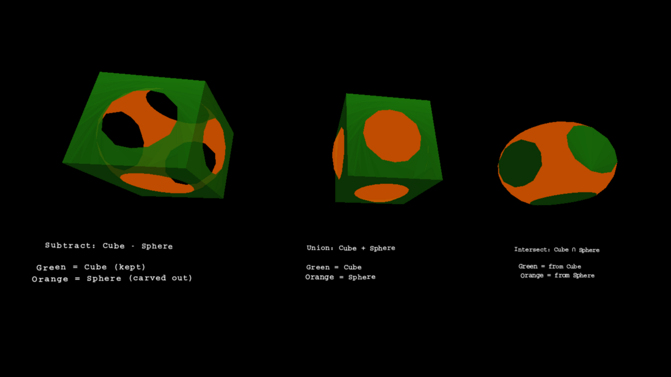
Aukio 3D allows performing boolean operations against geometry shapes. So one can subtract, unionize or intersect shapes.
To understand CSG boolean operations, read more about Constructive Solid Geometry.
1.5. SDF textures for sharp text
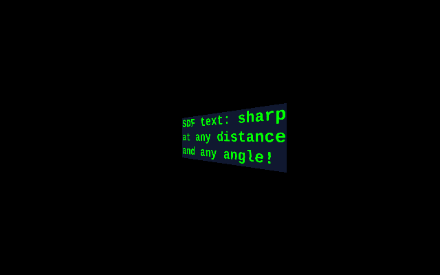
Text and vector-art surfaces do not store coverage; they store a signed distance field — per texel, the distance to the nearest glyph edge. The rasterizer re-derives coverage per screen pixel from that smooth field, so text stays sharp at any zoom and fades to clean gray under minification, all without a mipmap chain.
See SDF textures for the glyph pipeline, the render path, analytic minification and tuning knobs.
1.6. Octree voxel volumes and ray tracing
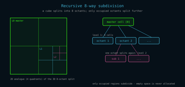
Beyond triangles, the engine can store a scene as a voxel volume in a flat-pool octree — and render it with a real ray tracer: one ray per pixel through the volume, per-pixel shadows from shadow rays, and progressive on-screen refinement.
See Octree ray tracing for the data structure, the traversal and how to run it.
1.7. Interactive GUI components
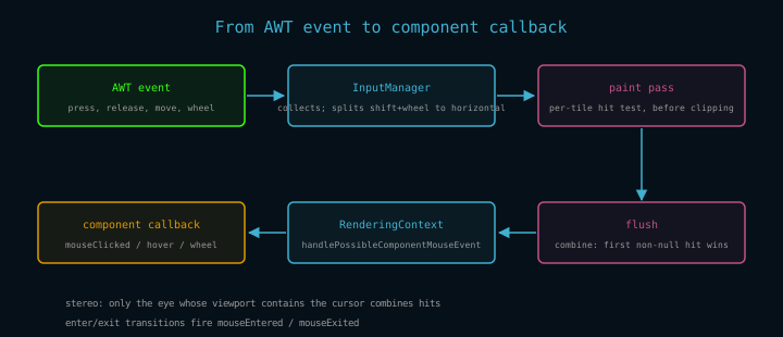
Widgets live in the world: clickable, focusable panels that receive keyboard input, with perspective-correct texture coordinates for every click and hover. A complete text editor is built on the same base class.
See GUI components for the focus model, event dispatch and the callback surface.
1.8. Wavefront OBJ model loading
Existing models in the Wavefront OBJ format load into the scene graph with one call:
ObjModel model = ObjLoader.load(Path.of("city1.obj"));
model.setShadingEnabled(true);
shapes.addShape(model);
ObjLoader (package
eu.svjatoslav.aukio.e3d.renderer.raster.shapes.composite.obj)
parses vertices, polygonal faces (all index forms, including forward
references from batch-flushing exporters), usemtl=/=mtllib material
references, and MTL Kd diffuse color + d opacity (translucent
materials blend in the alpha pass). Faces become SolidPolygon
instances inside an ObjModel composite, so transforms, shading and
backface culling work as for any composite. Coordinates load verbatim;
for standard +Y-up exports rotate the model 180° around X to stand
upright in the engine's -Y-up world.
If the source units do not match the scene's world scale, resize the model with the transform's uniform scale instead of editing the file — it applies about the model's local origin, before rotation:
model.setTransform(Transform.fromAngles(0, 0, 0, 0, Math.PI, 0));
model.getTransform().setScale(5.0);   // grow 5x
Transform.setScale works on any shape, not just loaded models: scale
is folded into the composed transform stack at push time, so per-vertex
render cost is unchanged and scenes that never set a scale render
bit-identically. Negative values mirror the geometry (flipping face
winding and thus backface culling).
See the OBJ loader city demo for a complete example.
2. How take engine into use
Add the Aukio 3D dependency to your Maven project:
<dependencies>
    <dependency>
        <groupId>eu.svjatoslav</groupId>
        <artifactId>aukio-3d</artifactId>
        <version>1.0.0</version>
    </dependency>
</dependencies>
Also add the repository (the library is not on Maven Central):
<repositories>
    <repository>
        <id>svjatoslav.eu</id>
        <name>Svjatoslav repository</name>
        <url>https://www3.svjatoslav.eu/maven/</url>
    </repository>
</repositories>
- Library requires Java 21 or newer.
- Study the demo applications for practical examples. Start with the minimal example to see the basic boilerplate needed to render a 3D scene.
- Study how Aukio 3D engine works.
- Read online JavaDoc.
- See Aukio 3D class diagrams. (Diagrams were generated by using JavaInspect utility)
2.1. Configuration
All Aukio programs share one YAML file, ~/.config/aukio/config.yaml.
Engine settings live in its e3d: section — stereo IPD, log and bug
report directories, telemetry interval — and every key can be
overridden with a -D system property for a single run.
See Configuration for the key table, live reload and write safety.
3. Essential theory
3.1. Coordinate System (X, Y, Z)
Aukio 3D uses a left-handed coordinate system with X pointing right and Y pointing down, matching standard 2D screen coordinates. This coordinate system should feel intuitive for people with preexisting 2D graphics background.
| Axis | Direction | Meaning |
|---|---|---|
| X | Horizontal, positive = RIGHT | Objects with larger X appear to the right |
| Y | Vertical, positive = DOWN | Lower Y = higher visually (up) |
| Z | Depth, positive = away from viewer | Negative Z = closer to camera |
Practical Examples
- A point at
(0, 0, 0)is at the origin. - A point at
(100, 50, 200)is: 100 units right, 50 units down visually, 200 units away from the camera. - To place object A "above" object B, give A a smaller Y value than B.
Coordinates in this system are stored using the
Point3D class — a mutable container with public x, y, z fields
supporting vector operations like distance, rotation, and translation.
Vertices (see below) are positioned within this coordinate system.
The aukio-3d-demos project includes an interactive coordinate system reference showing X, Y, Z axes as colored arrows with a grid plane for spatial context.
3.2. Point3D and Vertex
Every 3D object is built from vertices — corner points that define the shape's geometry. A triangle has 3 vertices, a cube has 8, and complex meshes have thousands. The engine uses two related classes to represent points in 3D space, each serving a different purpose.
3.2.1. Point3D — Raw Coordinates
Point3D is the fundamental coordinate type throughout the engine. It
stores a position or vector with three public fields: x, y, z.
The class provides vector math operations: distance calculation,
rotation, translation, scaling, dot/cross products, and interpolation. Methods follow a fluent API convention where mutating
operations (like add, multiply) return this for chaining, while
non-mutating variants (like withAdded, withMultiplied) return new
instances.
Use Point3D for:
- Storing positions, vectors, or any raw 3D coordinate
- Distance and angle calculations between points
- Vector math (dot product, cross product, normalization)
- Rotating or translating positions before shape construction
Point3D p1 = new Point3D(100, 50, 200);
Point3D p2 = new Point3D(0, 0, 100);
double distance = p1.getDistanceTo(p2);                  // Euclidean distance
Point3D direction = p1.withSubtracted(p2).unit();        // New point: unit vector from p2 to p1
p1.rotate(new Point3D(0,0,0), Math.PI/4, 0);             // Rotate p1 in place, 45° in XZ plane
3.2.2. Vertex — Rendering-Ready Coordinates
Vertex wraps a Point3D and adds the coordinate spaces needed during
rendering. As a shape transforms through the render pipeline, each
vertex tracks its position in multiple spaces:
| Field | Purpose |
|---|---|
coordinate |
Original position in local/model space |
transformedCoordinate(ctx) |
Position relative to camera (after transform stack) |
onScreenCoordinate(ctx) |
2D screen pixels (after perspective projection) |
textureCoordinate |
Optional UV coords in pixel units (not normalized) |
normal |
Optional normal vector for CSG polygon splitting |
transformedCoordinate and onScreenCoordinate are accessor methods,
not plain fields: each vertex carries three slots for each, one per
pipeline projection slot, and the accessor picks the slot of the
context's current render pass. This is what lets the triple-buffered
pipeline transform the next frame while previous frames are still
being painted (see software pipeline).
During rendering, the vertex is transformed through all spaces: first applying the TransformStack to get the camera-relative coordinate, then projecting to 2D. Results are cached per frame per slot to avoid recomputing for vertices shared across multiple shapes.
Use Vertex when:
- Constructing triangles, polygons, or textured shapes
- Your geometry needs texture UV coordinates
- You're performing CSG boolean operations (requires
normal)
// Create a textured triangle (texture coordinates use pixel units)
// For a 256x256 texture: (0,0)=top-left, (256,256)=bottom-right
Vertex v1 = new Vertex(new Point3D(0, 0, 100), new Point2D(0, 0));
Vertex v2 = new Vertex(new Point3D(100, 0, 100), new Point2D(256, 0));
Vertex v3 = new Vertex(new Point3D(50, 100, 100), new Point2D(128, 256));
TexturedTriangle triangle = new TexturedTriangle(v1, v2, v3, texture);
3.2.3. When to Use Each
| Use Point3D | Use Vertex |
|---|---|
| Positioning shapes, cameras, lights | Building triangles and polygons |
| Vector math (distances, directions) | Texture-mapped geometry |
| Rotating or translating positions | CSG operations |
| Temporary calculations | Shapes that render through transform pipeline |
For simple shapes without textures, you can pass raw Point3D
coordinates directly to constructors — the shape will internally wrap
them in Vertex objects. The coordinate system above defines the
meaning of all x, y, z values in both classes.
3.3. Edge
An edge is a straight line segment connecting two vertices. Edges form the wireframe skeleton of a 3D model — the structural framework visible when surfaces are not rendered. A triangle has 3 edges, a cube has 12 edges, and complex meshes have thousands.
In Aukio 3D, the Line class implements edges as renderable shapes. Each Line connects two Vertex endpoints and stores two properties: a width in world units (adjusted for perspective during rendering) and a color with alpha transparency. The rendering algorithm switches between two modes based on the projected screen width: thin lines below the threshold are drawn as single pixels with alpha-adjusted coloring, while thicker lines are rendered as filled rectangles with perspective-correct edge fading using four LineInterpolator scanline boundaries.
Wireframe shapes are composite objects built from multiple Line instances. For example, WireframeBox creates 12 Line objects — four edges parallel to each axis — using a LineAppearance factory to ensure consistent styling across all edges. The WireframeCube convenience subclass provides a center-point constructor. See the Shape Gallery demo for a visual comparison of wireframe (edges only) versus solid polygon (surfaces with lighting) rendering modes.
3.4. Face (Triangle)
A face is a flat surface enclosed by edges — the visible skin of a 3D object. While faces can theoretically have any number of sides, 3D engines standardize on triangles because three points always define a flat plane. A quad (4 vertices) or pentagon (5 vertices) might be non-planar depending on vertex positions, causing rendering artifacts. Triangles avoid this problem entirely.
3.4.1. SolidPolygon — Solid-Color Faces
SolidPolygon is the primary face type, supporting any number of vertices (3 or more). Triangles render directly via scanline rasterization. N-vertex polygons (quads, pentagons, etc.) are triangulated using fan decomposition — a quad becomes 2 triangles, a pentagon 3 — but only when the polygon lives inside an AbstractCompositeShape (the scene graph root is one): the composite triangulates while building its render list. A standalone SolidPolygon with more than 3 vertices cannot be painted directly and throws IllegalStateException.
Each SolidPolygon stores a single fill color with optional alpha transparency. When shading is enabled, the lighting manager computes the polygon's illumination once during the transform phase, then applies the shaded color during painting. Backface culling (see Winding Order & Backface Culling) can be enabled per-polygon, or applied recursively to an entire composite shape via AbstractCompositeShape.setBackfaceCulling(true) — this propagates the setting to all SolidPolygon and TexturedTriangle sub-shapes, including nested composites.
// Create a red triangle
SolidPolygon triangle = SolidPolygon.triangle(
    new Point3D(0, 0, 100),
    new Point3D(50, 0, 100),
    new Point3D(25, 50, 100),
    Color.RED
);

// Create a blue quad (internally triangulated)
SolidPolygon quad = SolidPolygon.quad(
    new Point3D(-50, -50, 100),
    new Point3D(50, -50, 100),
    new Point3D(50, 50, 100),
    new Point3D(-50, 50, 100),
    Color.BLUE
);

// Enable lighting and culling for a closed mesh
quad.setShadingEnabled(true);
quad.setBackfaceCulling(true);

// Add to the scene — the root composite triangulates the quad
viewPanel.getRootShapeCollection().addShape(quad);
3.4.2. TexturedTriangle — UV-Mapped Faces
TexturedTriangle renders faces with image textures mapped via UV
coordinates. Each of the three vertices stores a textureCoordinate
(a Point2D with U and V values in pixel units matching the texture
dimensions). For a 256×256 texture, coordinates range from (0,0) at the
top-left corner to (256,256) at the bottom-right. During rasterization, the
engine interpolates these UV coordinates across the triangle's surface,
sampling the texture at each pixel. When mipmaps are used, the multiplicationFactor
scales coordinates to match the selected mipmap resolution.
The texture system supports mipmaps — pre-scaled versions of the texture selected based on the triangle's screen size to reduce aliasing artifacts on distant surfaces. Texture coordinates are mapped with perspective-correct interpolation inside the scanline rasterizer, so large triangles at steep angles render without distortion — see the perspective-correct textures page.
// Create a 256x256 texture
Texture texture = new Texture(256, 256, 2);  // width, height, maxUpscale

// Create a textured triangle with UV coordinates in pixel units
Vertex v1 = new Vertex(new Point3D(0, 0, 100), new Point2D(0, 0));      // top-left
Vertex v2 = new Vertex(new Point3D(100, 0, 100), new Point2D(256, 0));  // top-right
Vertex v3 = new Vertex(new Point3D(50, 100, 100), new Point2D(128, 256)); // bottom-center

TexturedTriangle triangle = new TexturedTriangle(v1, v2, v3, texture);
triangle.setBackfaceCulling(true);
Both SolidPolygon and TexturedTriangle extend AbstractCoordinateShape, which handles vertex transformation and depth sorting. See the Shape Gallery demo for a visual comparison of solid versus textured polygon rendering.
3.5. Normal Vector
A normal is a vector perpendicular to a surface. It tells the renderer which direction a face is pointing. Normals are critical for lighting — the angle between the light direction and the normal determines how bright a surface appears.
Use cases:
| Use case | API | Computation | Location |
|---|---|---|---|
| BSP/CSG operations | SolidPolygon.getPlane() → Plane.normal | Lazy-cached once | Plane |
| Per-frame shading | Plane.computeNormal() → cachedNormal field |
Recomputed every frame | SolidPolygon |
| Lighting calculation | LightingManager.computeLighting() | Uses normal via dot(L,N) |
LightingManager |
Implementation notes:
- Plane.computeNormal(): shared zero-allocation helper for computing normals from three points
- Plane: stores normals in Hesse normal form (normal + distance) for BSP spatial partitioning
- Vertex.normal: optional field for CSG polygon splitting (not used for rendering)
3.6. Mesh
A mesh is a collection of vertices, edges, and faces that together define the shape of a 3D object. Even curved surfaces like spheres are approximated by many small triangles — more triangles means a smoother appearance. A cube has 8 vertices forming 12 triangular faces, while a smooth sphere requires hundreds or thousands of triangles depending on the desired quality.
In Aukio 3D, meshes are built through composition rather than monolithic vertex/index buffers. The AbstractCoordinateShape class is the foundation for primitive shapes — each instance stores its own List<Vertex> directly. This includes SolidPolygon (N-vertex convex polygons, not limited to triangles), TexturedTriangle (UV-mapped triangles), and Line (wireframe edges). The AbstractCompositeShape class groups multiple shapes into a single object with its own position, rotation, and transform — useful for complex models that move or rotate together.
Complex meshes are constructed procedurally by adding primitive shapes during initialization. For example, SolidPolygonSphere generates triangles using a latitude-longitude grid: with 16 segments, it creates 960 SolidPolygon triangles by looping through rings and sectors, calling addShape() for each. The generic SolidPolygonMesh accepts any list of triangles, allowing custom geometry from procedural generation or external sources.
During rendering, several automatic optimizations occur. N-vertex polygons (quads, pentagons, etc.) are triangulated using fan triangulation inside the composite's render-list builder, converting an N-vertex polygon into N-2 triangles. Textured triangles render with perspective-correct texture mapping (see perspective-correct textures). Composites perform view frustum culling to skip rendering when entirely off-screen. Sub-shapes can be organized into named groups via SubShape wrappers, allowing showGroup() and hideGroup() to toggle visibility of entire sections. Composite shapes also support CSG boolean operations — see the Constructive Solid Geometry documentation for union, subtract, and intersect operations.
The Shape Gallery demo showcases all primitive shapes available in Aukio 3D, rendered in both wireframe mode (edges only via WireframeBox and similar) and solid polygon mode (filled surfaces with dynamic lighting).
3.7. Working with Colors
Aukio 3D uses its own Color class instead of java.awt.Color. This custom implementation is designed specifically for the engine's software rasterizer, where avoiding object allocation during rendering is critical for performance. When rendering thousands of polygons per frame, creating new Color instances for each one would generate excessive garbage and trigger frequent garbage collection pauses. Instead, the engine's Color class uses mutable fields that can be reused across frames.
The class stores RGBA components as public integer fields in the range 0–255. This format matches the engine's pixel buffer layout and avoids costly float-to-int conversions during rasterization. The r, g, b, and a fields are accessible directly, allowing lighting calculations and alpha blending to modify colors in-place without allocating new objects. For example, the SolidPolygon class maintains a reusable shadedColor field that gets updated during each frame's lighting calculation instead of creating a new Color instance per polygon.
Color provides several constructors for different input formats. The
most common approach is using hex strings via Color.hex(String) or the
String constructor, which support formats like "F80" (3-digit RGB),
"FF8800" (6-digit RGB), "F808" (4-digit RGBA), and "FF8800CC"
(8-digit RGBA). You can also create colors from integer RGBA
components (0–255) using new Color(r, g, b, a), from floating-point
components (0.0–1.0) via new Color(double r, double g, double b,
double a), or from a packed RGB integer like 0xFF8800 using new
Color(int rgb). The class also provides predefined constants for
common colors: Color.RED, Color.GREEN, Color.BLUE, Color.YELLOW,
Color.CYAN, Color.MAGENTA, Color.WHITE, Color.BLACK, and
Color.TRANSPARENT.
The set(int r, int g, int b, int a) method modifies a Color in-place
and returns this for method chaining, which is essential for
performance during rendering. For example, the LightingManager
calculates lighting contributions from all light sources and stores
the final shaded color directly into a reusable Color instance via
set(), avoiding any allocation. The toAwtColor() method converts a
Aukio 3D Color to a java.awt.Color when needed for Java2D graphics
operations, caching the result to avoid repeated conversion. The
toInt() method packs the color into an ARGB integer suitable for the
engine's pixel buffer, used during rasterization to write pixels
directly.
import eu.svjatoslav.aukio.e3d.renderer.raster.Color;
import static eu.svjatoslav.aukio.e3d.renderer.raster.Color.hex;

// Using predefined color constants
Color red = Color.RED;
Color transparent = Color.TRANSPARENT;

// Create from hex string (recommended for clarity)
Color orange = hex("FF8800");           // RGB, fully opaque
Color semiTransparent = hex("FF880080"); // RGBA, 50% transparent

// Create from integer components (0-255)
Color custom = new Color(255, 128, 64, 200);

// Create from packed RGB integer
Color packed = new Color(0xFF8800);

// Modify existing color in-place (no allocation)
Color reusable = new Color();
reusable.set(100, 200, 50, 255);

// Convert to AWT color for Java2D operations
java.awt.Color awtColor = custom.toAwtColor();

// Use in lighting calculations (LightingManager modifies in-place)
// See the Shading & Lighting documentation for details
The alpha component controls transparency during rendering. A value of
0 makes the color fully transparent, while 255 makes it fully
opaque. The rasterizer implements alpha blending during the paint
phase: when drawing a semi-transparent pixel, the engine blends the
source color with the existing background pixel proportionally based
on the alpha value. The TextureBitmap.drawPixel() method handles this
blending, multiplying source colors by alpha and background colors by
(255 - alpha), then combining them. You can test whether a color is
fully transparent using isTransparent(), which returns true when alpha
equals zero.
For lighting calculations, the LightSource class uses Color to represent the color and intensity of emitted light. Multiple light sources contribute to the final shaded color of each polygon, as described in the Shading & Lighting documentation. The ambient light provides base illumination that affects all surfaces equally, regardless of orientation. Colors are also used for wireframe rendering via the Line class, where the color field determines the line's appearance.
3.8. Shading & Lighting
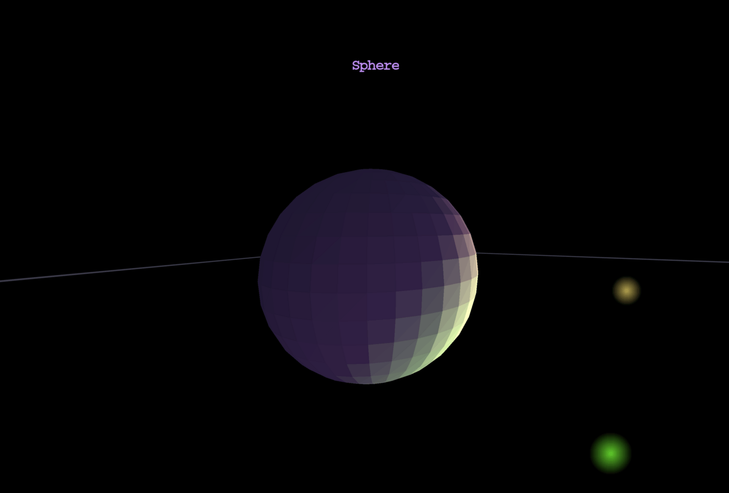
Aukio 3D implements flat shading — one normal per polygon, computed from the first three vertices. Each polygon receives a single color based on its orientation relative to light sources.
To understand lighting and shading, read more about shading & lighting.
4. 3D engine internals
4.1. Main render loop
The rendering loop is the heart of the engine, continuously generating frames at a target rate (typically 60 FPS). Each frame transforms 3D shapes through a multi-stage pipeline before displaying them on screen.
The render loop runs on a dedicated background daemon thread managed by ViewPanel, which can optionally sleep between frames to maintain a target FPS or run unlimited for benchmarking.
For a detailed walkthrough of each phase with diagrams and code examples, see the dedicated page: Rendering loop.
4.2. Near-Plane Clipping
Individual polygons that straddle the camera's near plane are not dropped wholesale: the vertex loop is clipped against the plane, new intersection vertices are generated with 3D-interpolated UVs and normals, and the clipped polygon — a triangle can become a quad, painted as a triangle fan — renders normally. Only polygons entirely behind the near plane are culled. This keeps floor and wall tiles visible when the camera brushes against them.
Read more about near-plane clipping.
4.3. Depth buffer
Visibility is resolved per pixel by a depth buffer: every triangle
interpolates 1/z across its spans and wins a pixel only where it is
nearer than the surface already there. Opaque geometry — textured
triangles, solid polygons — paints front-to-back with depth writes;
translucent geometry paints back-to-front with depth tests but no
writes, so it never occludes. Lines and billboards stay painter-ordered
overlays by design.
See Depth buffer for the full treatment.
4.4. Frustum & View Frustum Culling
Aukio 3D implements view frustum culling.
To understand frustum culling and object-level visibility optimization, read more about frustum & view frustum culling.
4.5. Subpixel culling
Distant geometry whose whole screen footprint is a fraction of a
pixel still costs full transform setup. Subpixel culling drops such
shapes right after their screen bounds are known, and caches the
verdict per shape so that stationary frames skip their setup
entirely. Off by default; enable with -Daukio.cull.subpixel=<px>.
Read more about subpixel culling — the verdict epoch, tuning knobs and measured effect.
4.6. Winding Order & Backface Culling
The order in which a triangle's vertices are listed determines its winding order. In Aukio 3D, screen coordinates have Y-axis pointing down, which inverts the apparent winding direction compared to standard mathematical convention (Y-up). Counter-clockwise (CCW) in screen space means front-facing. Backface culling skips rendering triangles that face away from the camera — a major performance optimization.
- CCW winding (in screen space) → front face (visible)
- CW winding (in screen space) → back face (culled)
- When viewing a polygon from outside: define vertices in counter-clockwise order as seen from the camera
- Saves ~50% of triangle rendering
- Implementation uses signed area:
signedArea < 0means front-facing (in Y-down screen coordinates, negative signed area corresponds to visually CCW winding)
In Aukio 3D, backface culling is optional and disabled by default. Enable it per-shape:
- SolidPolygon.setBackfaceCulling(true)
- TexturedTriangle.setBackfaceCulling(true)
- AbstractCompositeShape.setBackfaceCulling(true) (applies to all sub-shapes)
See the Winding Order demo for an interactive visualization.
4.7. Perspective correct textures
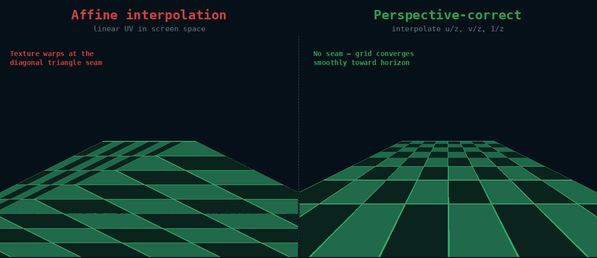
Aukio 3D tries to do perspective-correct texture rendering. Read more about perspective-correct texture implementation.
5. Developer tools
Press F12 anywhere in the application to open the Developer Tools panel:
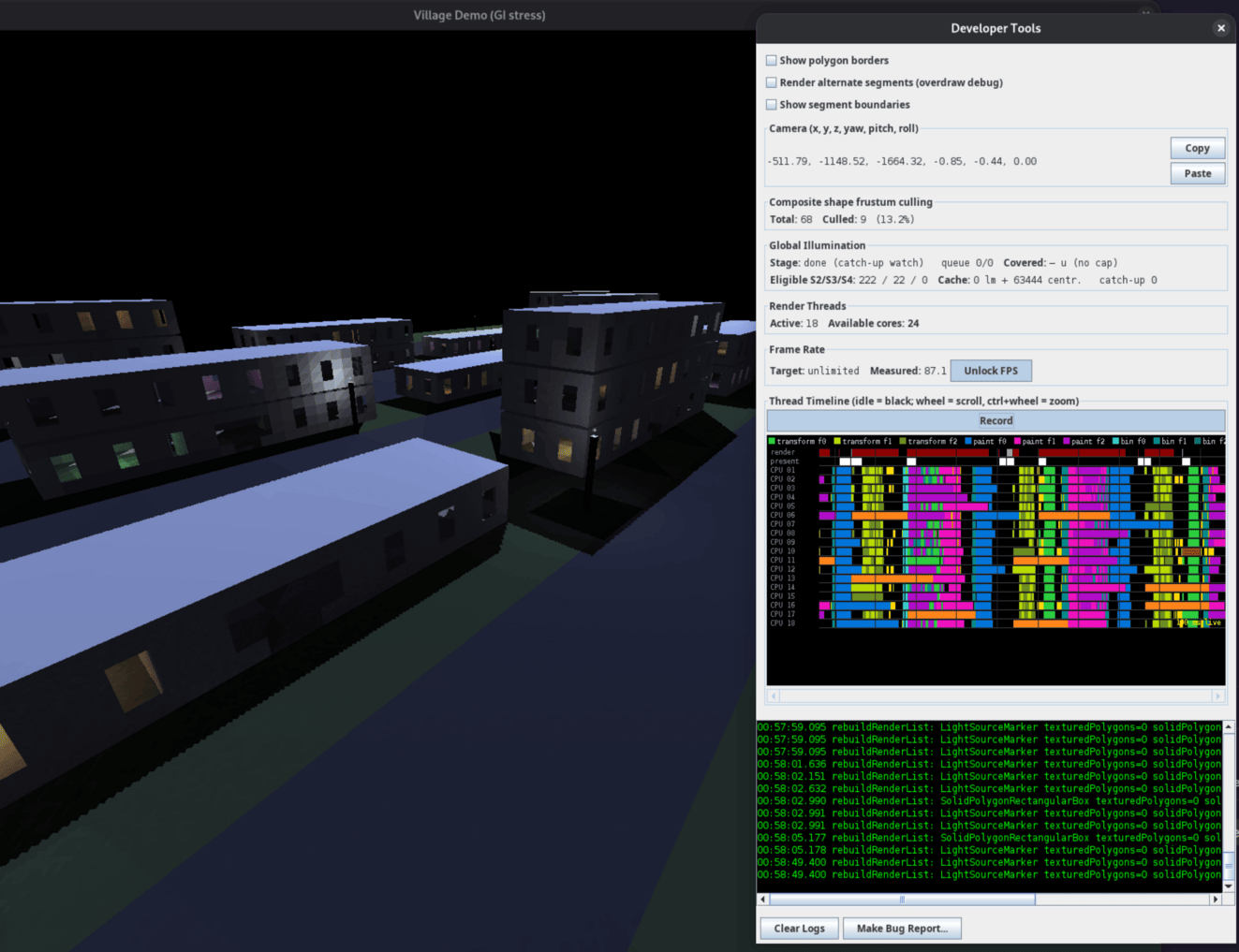
This debugging interface helps you understand what the engine is doing internally and diagnose rendering issues. Pressing F12 again closes the panel.
5.1. Diagnostic toggles
5.1.1. Show polygon borders
When enabled, each TexturedTriangle draws yellow outlines around its three edges after rendering its texture content. This overlays the triangle mesh onto the final image:
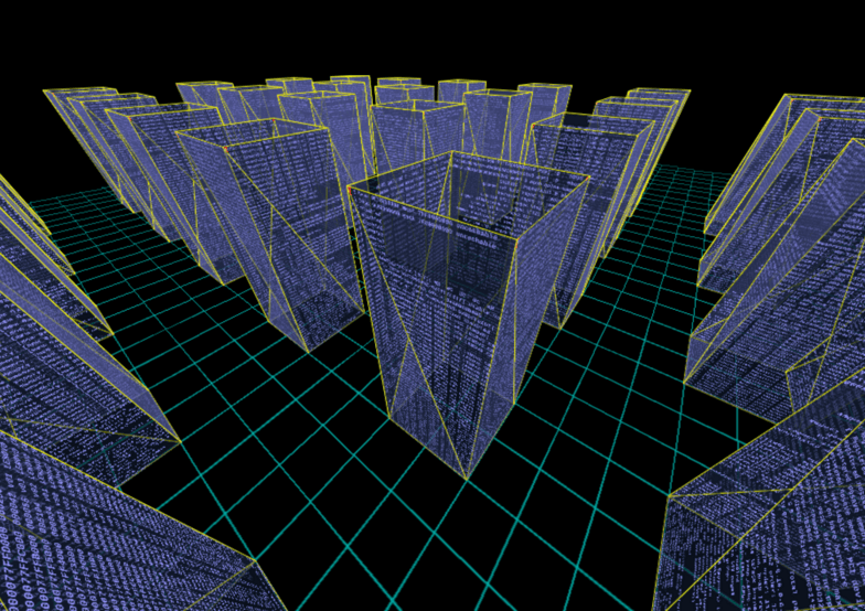
Use this visualization when investigating:
- Mesh structure: see the actual triangles as the rasterizer receives them
- Geometry bugs: spot T-junction gaps and overlapping geometry
- Texture distortion: compare triangle shapes against visible warping
5.1.2. Render alternate segments (overdraw debug)
Renders only even-numbered paint tiles while leaving odd-numbered ones black. (The screen is divided into a grid of rectangular tiles for parallel rendering — see the rendering loop documentation. "Segments" is the older name for tiles.)

This toggle helps detect overdraw: threads writing outside their allocated tile. If you see rendering artifacts in the black tiles, a paint task is writing pixels outside its assigned area — a clear sign of a bug.
5.1.3. Show segment boundaries
Draws red lines along the paint tile boundaries, making it easy to see exactly where each tile's rendered area begins and ends. In stereo mode each eye's viewport gets its own grid:
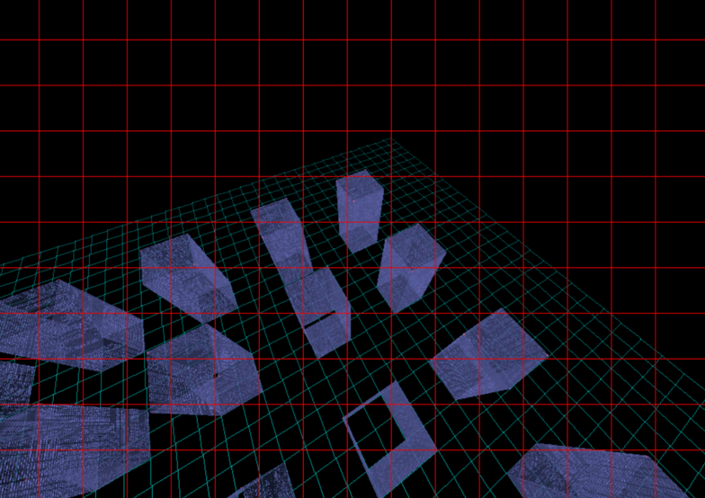
Useful for:
- Verifying the tile grid division
- Debugging tile-boundary rendering issues (e.g. clipped text or missing slivers at tile edges)
- Understanding the parallel rendering architecture visually
5.2. Camera position
Displays the current camera coordinates and orientation in real-time:
| Parameter | Description |
|---|---|
| x, y, z | Camera position in 3D world space |
| yaw | Rotation around the Y axis (left/right) |
| pitch | Rotation around the X axis (up/down) |
| roll | Rotation around the Z axis (tilt) |
The Copy button copies the full camera position string to the clipboard in a format ready to paste into bug reports or configuration files.
Use this for:
- Reporting exact camera positions when filing bugs
- Saving interesting viewpoints for later reference
- Understanding camera movement during navigation
- Sharing specific views with other developers
Example copied format:
500.00, -300.00, -800.00, 0.60, -0.50, -0.00
The six numbers map 1:1 onto Transform.set(x, y, z, yaw, pitch, roll), so a copied viewpoint can be restored at startup — this is how the demo applications freeze a good camera position into code:
// Camera position captured via Developer Tools -> Copy
viewPanel.getCamera().getTransform().set(
        130.66, -65.49, -248.18,   // x, y, z
        -0.06, -0.36, -0.00);      // yaw, pitch, roll
5.3. Frustum culling statistics
Shows real-time statistics about composite shape frustum culling efficiency (see the dedicated frustum culling page for how culling itself works):
| Statistic | Description |
|---|---|
| Total | Number of composite shapes tested against the frustum |
| Culled | Number of composites rejected (outside view frustum) |
| Culled % | Percentage of composites that were culled (0-100%) |
How to interpret the numbers:
- High cull % (60-90%): Excellent — most objects are being correctly culled
- Medium cull % (20-60%): Moderate — some optimization benefit
- Low cull % (0-20%): Limited benefit — either all objects are visible, or scene needs restructuring
Example:
Total: 473 Culled: 425 (89.9%)
This means 473 composite shapes were tested, 425 were outside the view and skipped entirely, and only 48 composites (with all their children) actually needed to be rendered. This is excellent culling efficiency.
The statistics update every 200ms while the panel is open. Note that the root composite is never frustum-tested (it's always rendered), so the "Total" count excludes it.
5.4. Global Illumination
Two status rows that report what the global
illumination system is doing, updated every 200 ms. The rows reflect
GlobalIllumination's
live Status snapshot, so they also respect per-instance radius
overrides — the numbers describe the effective configuration, not
just the global defaults.
Example (all four possible row states):
Stage: 3 (gen 12)   queue 1841/5202   Covered: 96 u / cap 150
Eligible S2/S3/S4: 222 / 22 / 0   Cache: 0 lm + 63444 centr.   catch-up 0
5.4.1. Stage line
Stage: <text> queue <done>/<length>
The stage text is one of:
| Text | Meaning |
|---|---|
disabled |
No GI system attached to the view (GI not enabled) |
starting… |
GI thread running but nothing baked yet (also shown when the entry count is 0) |
<n> (gen <g>) |
Bake in progress: currently baking stage n (1 = direct light + coverage; 2, 3, 4 = indirect bounce passes, tightest radius first) of generation g |
done (catch-up watch) |
Every entry fully baked; the GI thread is idle except for watching for newly streamed-in polygons that need catch-up baking |
queue <done>/<length> shows how many work items of the current stage
have been completed out of how many were queued. The queue is filtered
per generation (bugreport-20261005-212907): entries already holding a
current value are skipped when the queue is built, so a light change
or a newly streamed cell does not re-enqueue the whole world. While
done, the queue reads 0/0.
5.4.2. Coverage line
Covered: <d> u / cap <r> (or Covered: — u (no cap))
<d> u— how far from the camera, in world units, the bake has spread: the distance to the farthest polygon that already holds a fully baked value. Shows— uuntil the coverage walk has a measurement (briefly after startup or a light change)./ cap <r>— the radius cap of the currently active stage (stage 2/3/4 radius respectively), again the effective value after per-instance overrides.(no cap)means the active stage is unlimited (cap 0) — typically stage 1, which covers everything, or a stage whose radius was set to 0.
Watch this line to answer "is the light done spreading to where I'm
looking?": when <d> stops growing and reaches (or exceeds) the cap,
the visible scene is fully baked out to that stage's radius.
5.4.3. Eligible and cache line
Eligible S2/S3/S4: <a> / <b> / <c>
How many polygons fall inside each indirect stage's radius right now —
i.e. how much work each remaining bounce pass still has to do. These
counts move as you walk around (streaming changes what is near) and as
radii are reconfigured. All zeroes with a non-done stage means the
bake is draining its current queue and will advance shortly.
Cache: <n> lm + <m> centr. catch-up <k>
<n> lm— entries in the lightmap cache (LightmapCache, see Lightmaps: a texture per triangle): fully baked lightmaps kept by their light signature, so a polygon whose light inputs have not changed never re-rasterizes its lightmap.<m> centr.— entries in the centroid cache: per-polygon stage-1 and stage-2 results (direct RGB, indirect RGB, delta and visibility bits) keyed by geometry identity. A polygon that streams out and back in — the normal case in a streamed world — restores both finished stages from RAM and is never recomputed twice within a run. The cache is capped at 4,000,000 entries by default (≈ 0.5 GB worst case, sized for a fully streamed FO4 world), tunable viae3d.gi.centroidCacheEntries/-De3d.gi.centroidCacheEntries.catch-up <k>— polygons that arrived after their generation was already baked (streamed in late) and are queued for catch-up baking. A nonzero value here while the stage line saysdone (catch-up watch)is normal right after fast movement; it should drain back to 0 within seconds. If it never drains, those polygons are being re-discovered faster than the catch-up thread bakes them.
5.5. Render threads
Shows the number of active render threads versus available CPU cores. The engine defaults to 75% of available threads (at most cores − 1, so one thread always stays free for the rest of the system). The count is changeable at runtime via ViewPanel.setNumRenderThreads(int); the worker pool is recreated lazily on the next frame.
5.6. Frame rate
Shows the current target FPS and the measured production rate (frames completed per second, averaged over a ~500 ms window). The measured number counts produced frames regardless of how quickly the display path presents them — see frame rate control.
The Unlock FPS toggle switches to unlimited (benchmark) mode: the engine renders continuously as fast as possible, even when the scene is static. Toggling off restores the previously locked target rate.
5.7. Thread activity timeline
A per-thread occupancy view — the software-renderer equivalent of a GPU frame profiler. Each thread gets a row (the render thread and present thread on top, then one row per worker), time runs along the X axis, and each colored block is one recorded work interval. Idle time is black.
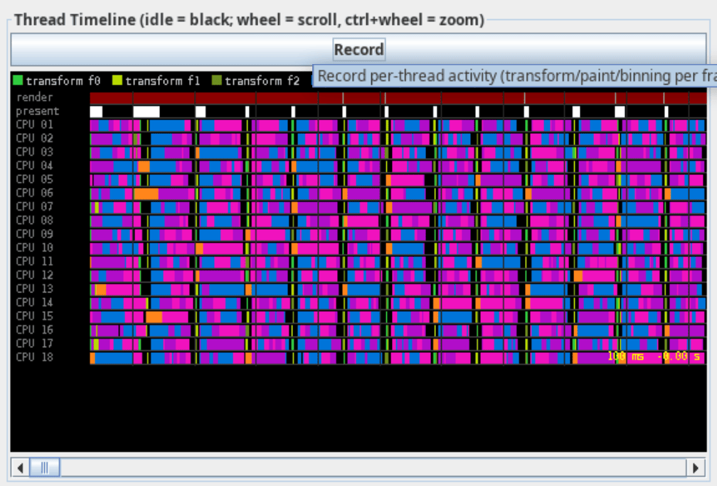
Press Record to start capturing. The colors encode both the task kind and which frame the task belongs to — transform, paint, and binning come in three frame-parity variants (f0/f1/f2), so you can see up to three frames in flight simultaneously. Additional colors mark render-thread orchestration, blocked time, blits, and the sort/drain sub-phases.
Navigation: mouse wheel scrolls, Ctrl+wheel zooms, and a scrollbar moves along the captured range.
The legend colors, exactly as the timeline paints them:
| Color | Legend label | What it shows |
|---|---|---|
#2ECC40 |
transform f0 |
Vertex transform chunk task, frame slot 0 |
#B8D900 |
transform f1 |
Vertex transform chunk task, frame slot 1 |
#6B8E23 |
transform f2 |
Vertex transform chunk task, frame slot 2 |
#0074D9 |
paint f0 |
Paint tile task (clear + rasterize one tile), frame slot 0 |
#F012BE |
paint f1 |
Paint tile task, frame slot 1 |
#B10DC9 |
paint f2 |
Paint tile task, frame slot 2 |
#39CCCC |
bin f0 |
Tile binning task (assign sorted shapes to tiles), frame slot 0 |
#008B8B |
bin f1 |
Tile binning task, frame slot 1 |
#007070 |
bin f2 |
Tile binning task, frame slot 2 |
#A0A0A0 |
render serial |
Render thread orchestration: tree walk and pass submission |
#8B0000 |
blocked |
Render thread waiting for an older paint pass or the present gate |
#FFFFFF |
blit |
Present thread copying a finished frame to the screen |
#FF851B |
sort+bin |
A pass's async continuation as a whole: drain, sort, bin, submit paint |
#8B4513 |
drain |
Continuation sub-phase: await and merge parallel transform chunks |
#FFD700 |
sort |
Continuation sub-phase: depth sort of the pass's shapes |
The f0/f1/f2 suffixes are the frame's projection slot (frame number
modulo 3) — the triple-buffering from the software pipeline.
When the pipeline is healthy you see interleaved colors from two or
three frames on the worker rows at once: paint tasks of an older frame
overlapping transform and binning of the newer one. Wide blocked
spans on the render row, or worker rows with black gaps, mean the
pipeline is starved rather than busy.
Recording is cheap but not free (~100 ns per task; a single volatile read when disabled), so leave it off during benchmarking runs. The captured intervals live in a fixed-size ring buffer — long recordings keep only the most recent history.
What to look for:
- Solidly packed worker rows mean the pipeline is keeping all cores busy — the design goal (see software pipeline)
- Long "blocked" spans on the render row mean the render thread is waiting for paint passes — workers are the bottleneck
- Long "blit" spans on the present row mean the display path (X server) is the bottleneck; excess frames are being dropped from the presentation mailbox
5.8. Live log viewer
The scrollable text area shows captured debug output in real-time:
- Green text on black background for readability
- Auto-scrolls to show latest entries
- Updates every 200ms while panel is open
- Captures logs even when panel is closed (replays when reopened)
Use the Clear Logs button to reset the log buffer for fresh diagnostic captures.
5.9. Make Bug Report
The Make Bug Report… button (next to Clear Logs) asks "What
happened / what looks wrong?" and then writes a self-contained
bugreport-<timestamp> directory (default root
~/.local/share/aukio/bugreports, configurable via
bugreport.dir / -De3d.bugreport.dir) you can hand to a developer — or to an AI assistant,
which can work through it fully automatically:
| File | Contents |
|---|---|
description.txt |
The text typed into the popup |
info.txt |
Camera pose, view/screen resolution, heap, telemetry snapshot, java/os versions, effective config |
screenshot.png |
A copy of the last rendered frame |
aukio.log / aukio.log.1 |
Persistent logs, including output from a session that froze before the report could be made |
histogram.txt |
Live-object histogram from jcmd <pid> GC.class_histogram (the OOM smoking gun; skipped when jcmd is unavailable) |
threads.txt |
Full thread dump for hang diagnosis |
The camera = (...) line in info.txt is the authoritative pose —
paste it straight into a headless reproduction
(Snapshot, Fo4Shot's -Daukio.fo4.spawnAt) to render
exactly what the reporter saw. After writing, a dialog shows the
report path with Copy Path and Open Folder buttons.
5.10. Headless & agentic tooling
For windowless rendering, pixel assertions, golden-image regression tests and scene dumps — built for automated verification and AI agents — see agentic development tools.
6. Agentic development
Aukio 3D provides good support for automated AI coding agents (for example OpenCode, Hermes Agent, etc..).
Thanks to facilities is eu.svjatoslav.aukio.e3d.headless package, an
AI agent can render any scene from any pose, assert what got painted,
compare against committed reference images, and dump the full scene
state for a bug report — all without a window, a display, or the
render thread.
6.1. One pipeline, two drivers
The key design decision: the headless path drives the very same transform → sort → paint pipeline the on-screen ViewPanel uses. Nothing is reimplemented, so a passing headless test proves the real render works, and a bug reproduced headlessly is the real bug.
Making this possible required three small engine changes:
ShapeCollection.transformShapes(Camera, RenderingContext)— the transform phase now accepts a camera directly; the ViewPanel variant just forwards its camera. Headless code never touches Swing.RenderingContext.getImage()— hands out the backing BufferedImage the rasterizer paints into.GlobalIllumination.isRunning()/isConverged()/getWorkItemCount()— GI state became inspectable.
6.2. Snapshot: render without a window
import eu.svjatoslav.aukio.e3d.headless.Snapshot;

ShapeCollection scene = new ShapeCollection();
scene.addShape(myShape);
LightingManager lighting = new LightingManager();
lighting.setAmbientLight(Color.hex("181818"));

// One call: build context, transform, sort, paint, return the image.
BufferedImage image = Snapshot.render(scene, lighting,
        "290.31, -35.59, -2.10, -0.58, -0.15, 0.0", 640, 480);
Snapshot.save(image, "/tmp/snapshot.png");
The pose string is the same "x, y, z, yaw, pitch, roll" format the
demos print and users quote in bug reports — paste the pose, reproduce
the exact view. Snapshot.cameraFromPose() and Snapshot.poseString()
convert in both directions.
For tests that need to detect unpainted pixels (holes), the
renderInto() variant fills the background with a caller-chosen
sentinel color first, so "nothing was painted here" is unambiguous even
in a pitch-black scene:
RenderingContext ctx = new RenderingContext(640, 480, 1);
ctx.lightingManager = lighting;
Snapshot.renderInto(scene, camera, ctx, 0x00010203); // sentinel
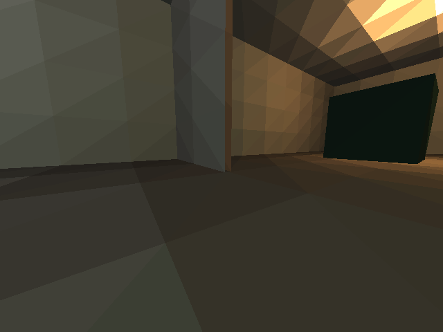
A real headless render — the House demo from a bug-report pose:
6.3. PixelAssertions: did this region get painted?
The recurring debugging question — "did the floor actually render, or did clipping eat it?" — becomes a library call:
import eu.svjatoslav.aukio.e3d.headless.PixelAssertions;

// Fraction of a relative rectangle still equal to the background:
double holes = PixelAssertions.unpaintedFraction(image, 0,
        0.15, 0.45, 0.85, 1.0);   // lower-center band
if (holes > 0.05)
    throw new AssertionError("floor has holes: " + holes);

long red = PixelAssertions.countColor(image, 0xFF0000);   // flat-color tests
String grid = PixelAssertions.dumpPixelGrid(image, 320, 240, 3, 8); // hex dump
6.4. GoldenImage: compare against a reference
A pixel counts as different when any RGB channel drifts more than a per-channel tolerance; the comparison fails when the fraction of differing pixels exceeds a threshold. Deterministic flat-shaded renders can use tight tolerances (4, 0.005); noisier paths relax them.
import eu.svjatoslav.aukio.e3d.headless.GoldenImage;

GoldenImage.Result r = GoldenImage.compare(actual,
        new File("goldens/house-flat.png"), 4, 0.005);
if (!r.passed)
    GoldenImage.saveDiff(actual, goldenFile, "/tmp/diff.png"); // red = differs
There is also a CLI for shell scripts — exit 0 = match, 1 = differ:
java eu.svjatoslav.aukio.e3d.headless.GoldenImage actual.png golden.png 4 0.005
A real diff: the house rendered with the living-room lamp removed, compared against the golden. The red region is exactly the room that lost its light:

6.5. SceneDump: the reproducible bug report
One call produces everything needed to reproduce what a frame shows:
System.out.println(SceneDump.dump(scene, lighting, camera, gi));
== SceneDump ==
shapes: 5 top-level, 546 queued for rendering
lights: 4 (ambient #181818)
  [0] pos=(-800.0, -240.0, 0.0) color=FFD890 intensity=6.0
  [1] pos=(0.0, -240.0, 0.0) color=D8E4FF intensity=5.0
  [2] pos=(800.0, -240.0, 0.0) color=FFB060 intensity=6.0
  [3] pos=(250.0, -60.0, -250.0) color=60FF90 intensity=2.0
camera: 290.31, -35.59, -2.10, -0.58, -0.15, -0.00
GI: running, 152034 work items, converged
The camera line is a pose string — it feeds straight back into
Snapshot.render().
6.6. HouseGoldens: ready-made regression tests
The aukio-3d-demos repo contains a working example of all of the above:
eu.svjatoslav.aukio.e3d.examples.goldens.HouseGoldens renders the
House demo at two poses (the default view and the near-plane straddle
bug pose), compares both against committed goldens, and independently
asserts the floor has no holes.
cd aukio-3d-demos
mvn clean package
mvn -q dependency:build-classpath -Dmdep.outputFile=cp.txt
java -cp "target/classes:$(cat cp.txt)" \
  eu.svjatoslav.aukio.e3d.examples.goldens.HouseGoldens           # verify
java -cp "target/classes:$(cat cp.txt)" \
  eu.svjatoslav.aukio.e3d.examples.goldens.HouseGoldens --update  # regenerate goldens
Exit code 0 = all pass, 1 = any mismatch (with a diff PNG in /tmp).
Demos that want the same treatment expose their scene construction:
HouseDemo.buildHouse(), addFurniture() and addLights() are public
for exactly this reason.
6.7. export-docs.sh: regenerate the documentation
All engine documentation (the pages you are reading) lives as org-mode
files under doc/. One script exports every page to HTML with the
darksun theme:
doc/export-docs.sh            # export all pages
doc/export-docs.sh --check    # + render every page with headless Chrome
                              #   to /tmp/doc-check-*.png for visual review
The --check mode is how an agent verifies its own documentation: SVG
label collisions, broken image links and table breakage all show up in
the rendered screenshots.
6.8. A typical agent session
1. Reproduce:   Snapshot.render(scene, lighting, bugReportPose, 640, 480)
2. Inspect:     SceneDump.dump(...) + view the PNG
3. Fix the engine
4. Verify:      PixelAssertions.unpaintedFraction(...) == 0
5. Regression:  HouseGoldens  (must stay ALL PASS)
6. Document:    edit doc pages, export-docs.sh --check, review shots
7. Source code
This program is free software: released under Creative Commons Zero (CC0) license
Program author:
- Svjatoslav Agejenko
- Homepage: https://svjatoslav.eu
- Email: mailto://svjatoslav@svjatoslav.eu
- See also: Other software projects hosted at svjatoslav.eu
Getting the source code:
- Download latest source code snapshot in TAR GZ format
- Browse Git repository online
Clone Git repository using command:
git clone https://www3.svjatoslav.eu/git/aukio-3d.git